YouTube player

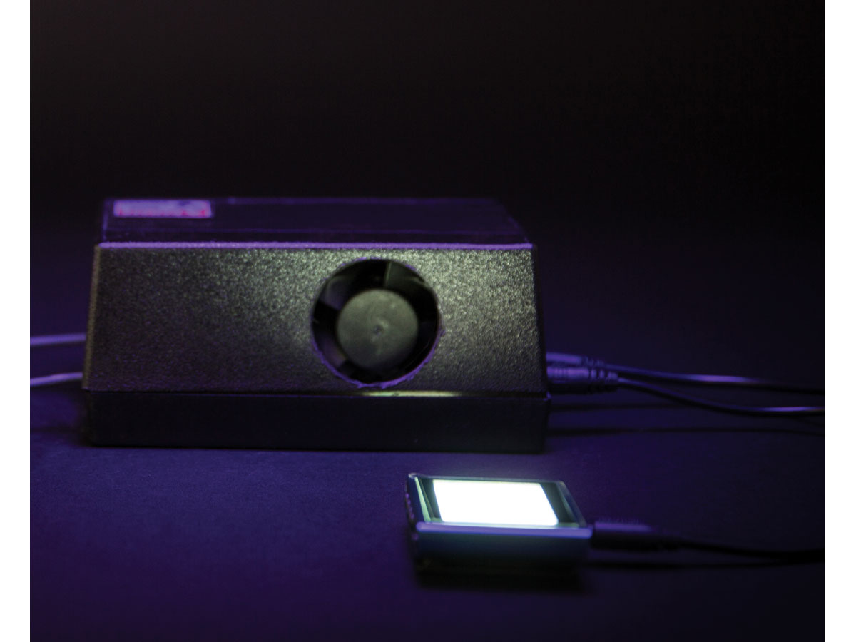
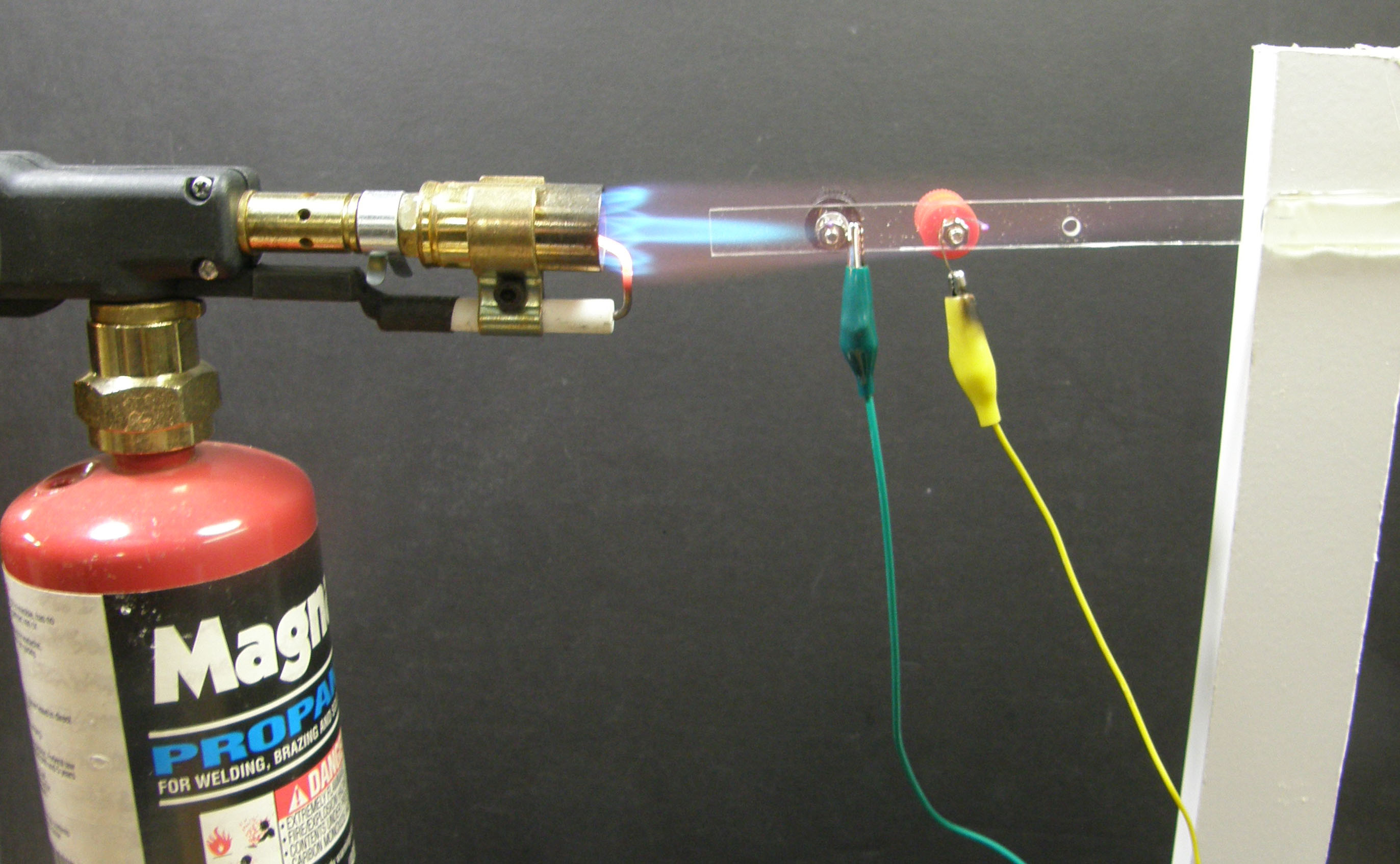
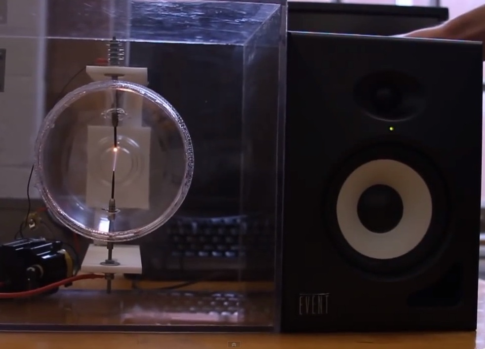
What do the world’s most expensive speakers, the sun, and lamps from the 1890s have in common? Plasma, the fourth state of matter, of course! After building this little plasma arc speaker, you’ll be able to hear your favorite jams played directly from the vibrating plasma of an electric arc.

Plasma is a high-temperature, highly ionized gas that’s electrically conductive. While conventional loudspeakers use a solid diaphragm, the plasma arc speaker uses ionized gas as a gaseous diaphragm — it’s virtually massless, so it easily responds to high-frequency audio signals. By varying the electrical signal across the electrodes, you’ll cause the ions in the plasma to jiggle, which causes the gaseous diaphragm to vibrate and create sound waves in the air.

2_m44_PlasmaArcSpeakeronBlack

The Singing Arc

The first instance of a plasma arc speaker can be traced back to William Duddell in 1899. Duddell connected an ordinary carbon arc lamp to a tuned circuit made of a capacitor and inductor, and he discovered that he could generate tones that corresponded to the resonant frequency of the tuned circuit. He wired a keyboard and played “God Save the Queen” on what is considered the first electronic musical instrument — the “singing arc.”

How It Works

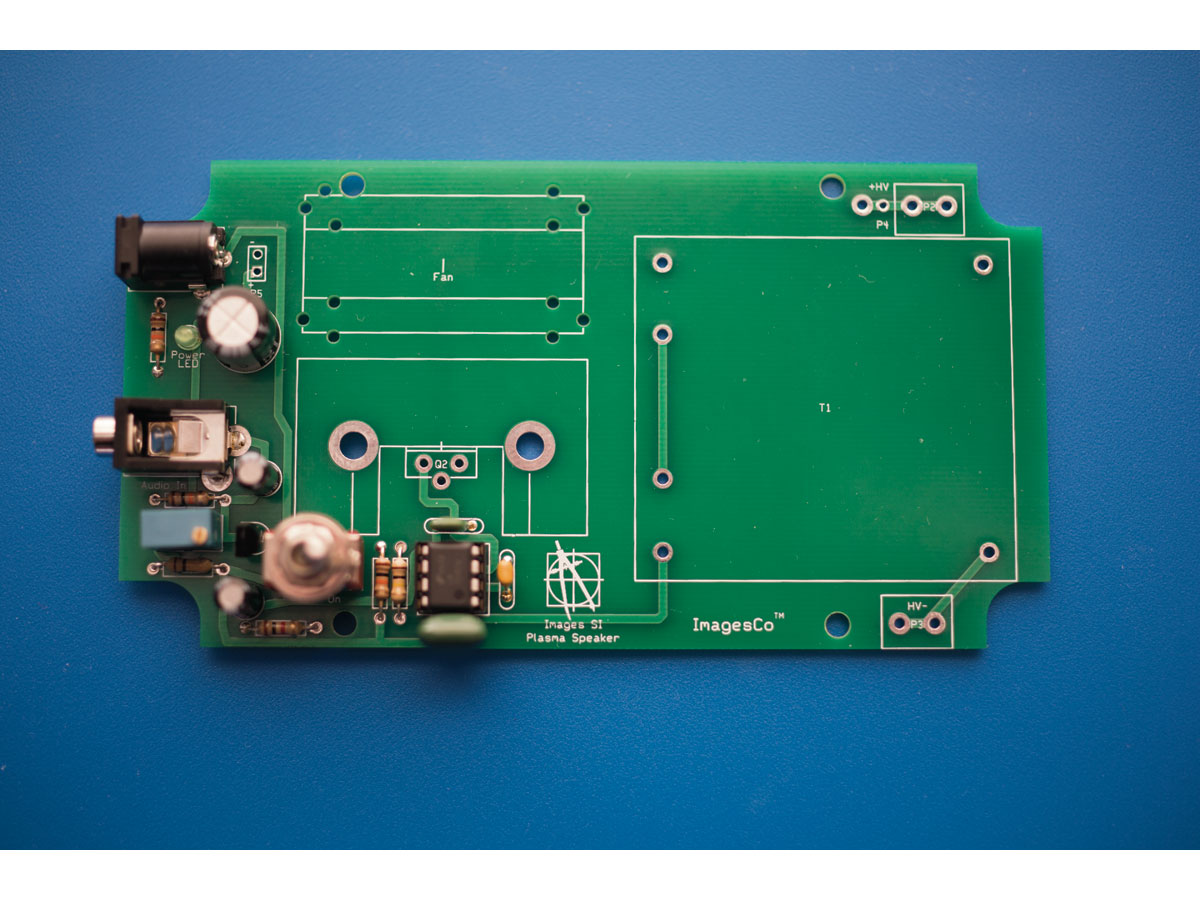
Most modern published schematics for building “singing arc” speakers use either a 555 timer or a TL494 PWM controller, whose output is wired to a standard power transistor or MOSFET to rapidly switch current on and off to the high-voltage (HV) transformer. I chose to use a 555 timer with a unique power component, the insulated-gate bipolar transistor (IGBT), which is ideally suited for this application. It’s got the high current capacity of a bipolar transistor and the voltage control of a MOSFET.

plasmaspeaker_schematic_v1

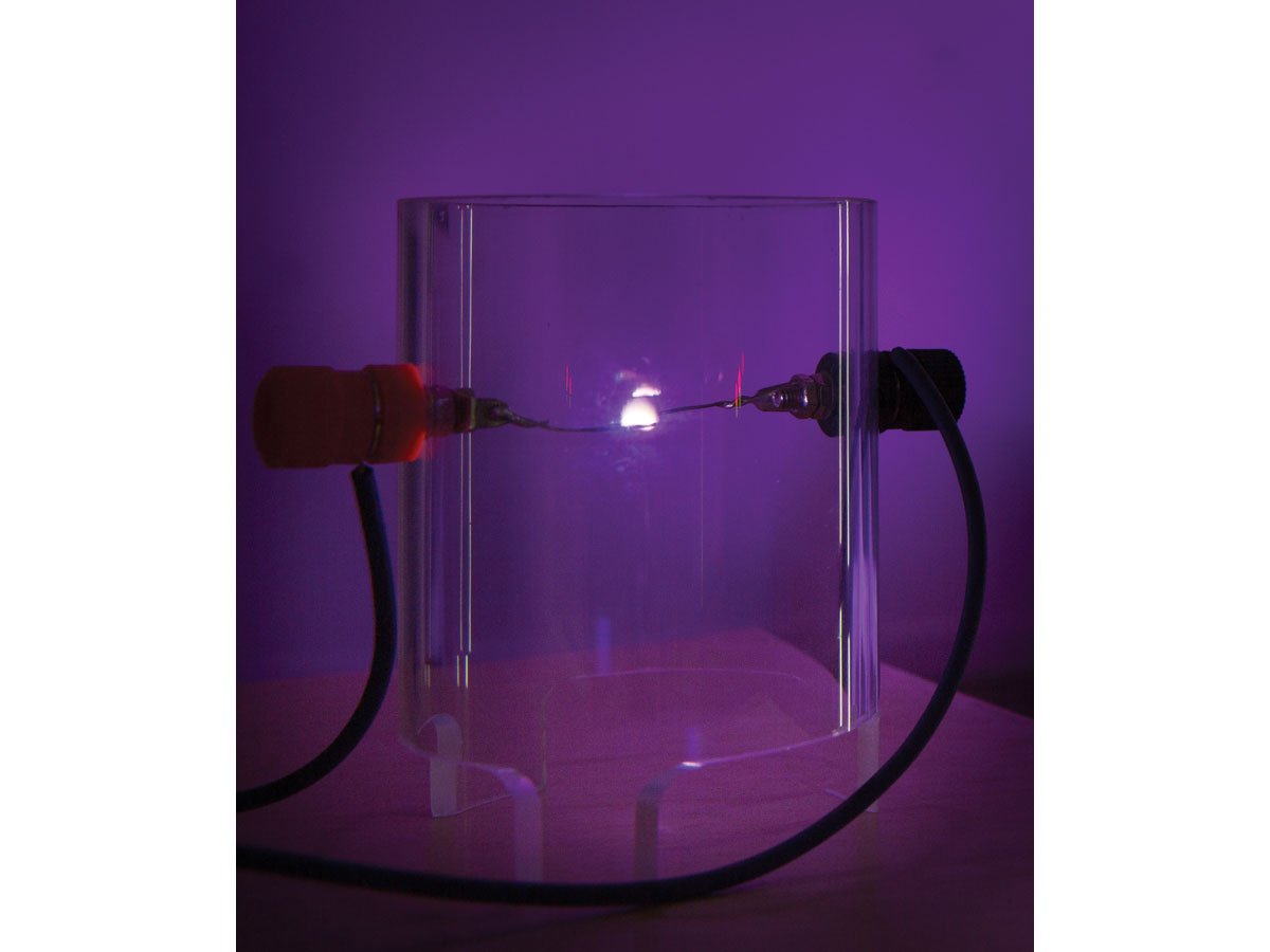
The 555 timer is set up in astable mode to continually output a frequency dependent upon an RC network composed of two resistors and a capacitor. This is the oscillation frequency that powers the HV transformer. I chose a “base frequency” of approximately 23kHz because it allows the HV transformer to create an output arc (plasma) that doesn’t produce any sound or tone on its own, as this would detract from the sound quality of the speaker.

Pin 5 on the 555 timer is the control voltage input. By applying a voltage to this pin, we can vary the output frequency of the timer independently from the base frequency that’s set by the RC network. This creates a frequency modulation (FM) output, like FM radio. Just connect the audio output from the 2N3904 transistor to pin 5, and now your audio signal is modulating the output frequency of the 555 timer. This FM output, amplified by the HV transformer, is what jiggles the ions in the plasma arc to create sound.

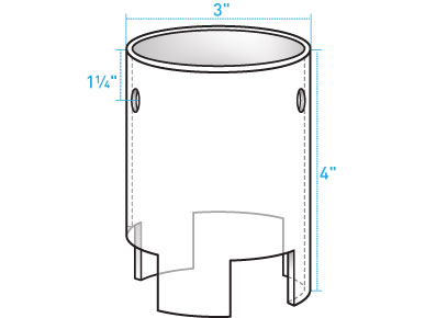
This small speaker is the equivalent of a tweeter. Large electric arcs can produce better fidelity at lower frequencies, but the smaller arcs in this device are better at reproducing sound in the higher frequencies.
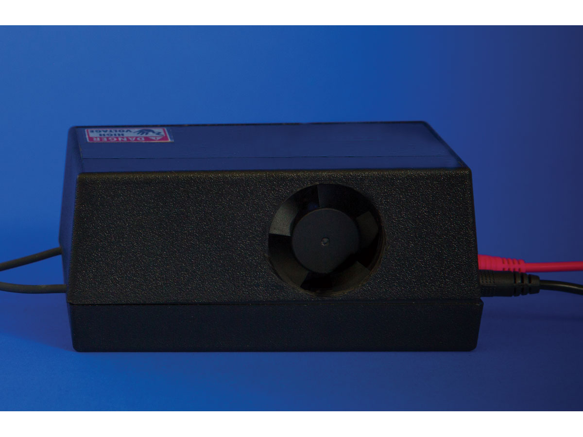
CAUTION

Plasma speakers are high-voltage devices. If you’re not familiar with working with high-voltage devices, we do not recommend you build this device. High voltage can be lethal. If you have a weak heart or have a biomedical implanted device like a pacemaker, do NOT build this device. Safe assembly and operation of this project is the user’s responsibility.

A high voltage may cause you to jump, move, or fall, and can thereby cause a secondary injury, unrelated to the electric shock itself. I personally have been shocked many times by various high-voltage circuits, including this one. Take the following precautions and treat all high-voltage power supplies with the respect they deserve.

Basic Safety Guidelines

Follow these simple guidelines and rules to stay safe.

  • Keep one hand in your pocket. Only use your other hand to work with the high-voltage equipment. This reduces the probability of accidentally passing high-voltage current across your heart from hand to hand.
  • Set up your work area away from possible grounds that you may accidentally contact. Keep your work area neat and clean to easily identify high-voltage wires and grounds.
  • Be sure the floor is dry and wear preferably rubber-soled shoes.
  • Prove to yourself the high-voltage power supply is off, by unplugging the device’s electrical power cord. Don’t trust power switches that could be hit or pressed and accidentally turned on.
  • Discharge all high voltage before working on the device. This means attaching a wire to the circuit ground and touching the high-voltage output terminal with the grounded wire. This will dissipate any stored high-voltage charge.
  • Do not work on high-voltage apparatus when you are tired and not alert, even if it means a delay.
  • There is a chance that the high voltage could jump to the low-voltage side of the circuit and damage the audio player device. Use only inexpensive audio devices. We are not responsible for any damage to your audio devices.
  • Do not operate the equipment if there’s any evidence of damage to the circuit or speaker discharge unit.
  • Ultraviolet light generated by the electrical arc may cause eye irritation. Wear eyeglasses or sunglasses made of common glass, which absorbs UV.
  • Use in a ventilated area to prevent ozone build-up. Ozone concentrations of 0.5 to 1.0 PPM could produce throat irritation in sensitive individuals.

Project Steps

Build the circuit

Solder the components to the printed circuit board (PCB) included in the kit. If you’re not using the kit, you can prototype the circuit using point-to-point wiring, following the schematic. You can use a solderless breadboard for the low-current components only, like the 555 timer, 2N3904 transistor, and audio input. (While the circuit as a whole draws less than 2A of current, that’s still above the rating of solderless breadboards.)

NOTE: If you’re using a different HV transformer, you may need to adjust the base frequency of the 555 timer in order to achieve a “silent” high-voltage plasma arc. Experiment with the resistor and capacitor values of the RC network (R5, R6, and C3) to tune the base frequency until a silent electrical arc is achieved.

Spread heat sink compound on the back of the IGBT and make sure there’s good contact with the heat sink to ensure good heat transfer.

Mount it in the enclosure

The output of this circuit generates high voltage — be careful near the output of the HV transformer! — so you’ll mount it in a plastic enclosure, as plastic is an insulator and will be safer than a metal enclosure. First, connect the high voltage wires to the output of the HV transformer; you will run these out to the binding posts of the plasma speaker tube.

IMPORTANT: The large IGBT heat sink and 12VDC blower fan are essential. Mount the fan close to the heat sink to maximize cooling, and make sure your enclosure has large circular cutouts for intake and exhaust to permit sufficient airflow for cooling. Without taking these actions, your IGBT will overheat in less than a minute.

Drill and cut holes in the enclosure for the fan venting, power jack, audio input, LED, switch, and high voltage wires, following the template.

Build the plasma speaker tube

The speaker is fabricated out of a 4″ length of 3″-diameter clear plastic tubing. Cut 3 notches in the bottom of the plastic tube to create legs and to allow airflow. (The arc can get as hot as a candle.)

Drill holes on opposite sides of the tube, 1-1/4″ from the top, sized to accept the binding post terminals.

Attach the electrodes

To make the electrodes, solder a length of 22–20 gauge solid wire to the solder tab of the binding post terminal. If your terminal doesn’t have a solder tab, simply wrap the wire around the inside binding post screw.

Secure each binding post with a nut, then attach the high-voltage wires from the trans-former.

Prepare the circuit for audio input

By turning potentiometer R3 with a small screw-driver, you can fine-tune the bias for the audio signal to the NPN transistor amplifier. Adjust potentiometer R3 to its midpoint position before turning on the plasma arc speaker.

The audio input signal I used was 100mV (0.1V) peak to peak from an iPod. If the audio signal is too large it will be clipped, creating distortion in the plasma speaker’s output. If your plasma arc speaker sounds terrible, the first thing to do is to reduce the volume of your audio signal going into the circuit. Less may be more.

Rock some tunes!

Before you turn on your plasma arc speaker for the first time, adjust the electrodes so the wires are arced and the ends of each wire face each other. This is to ensure that the electric arc forms between the wire ends, which will provide the best audio quality. If the arc travels up and down the side of the wire, you’ll hear distortion. Adjust the gap between the wire ends to approximately 1/4″.

Then connect your audio player to the circuit’s audio input, and press Play.

Power up the speaker, and adjust the volume as necessary to form an arc. If an arc doesn’t form, make sure audio is being played. If the arc still doesn’t form, switch the speaker off, unplug it, and then adjust the gap as necessary.

With your plasma arc speaker, you’ll be rocking tunes with the same technology that high-dollar audiophile speakers use!

Further Experiments: The Flame Speaker

In 1968, Popular Electronics magazine published an article titled “Flame Loudspeaker” describing the work of the three scientists A.G. Cattaneo, Wayne Babcock, and K.L. Baker. This article described using a high-temperature flame (low-temperature plasma) as the gaseous membrane to generate sound. The experimenters used an oxygen-acetylene torch to create a high-temperature flame. Cooler flames from a propane torch could be used, but needed to be seeded with an easily ionized material such as potassium nitrate to generate a useable amount of low temperature ions. Seeding also increased the volume output of the high-temperature flame speaker. Two tungsten electrodes were inserted into the heart of the flame, a few inches apart from one another, and the audio signal was boosted to 300 to 500 volts in order to jiggle the low temperature plasma to tease out some sound.

A flame speaker is similar in operating principle to the electric arc speaker, so I wondered if the Plasma Arc Speaker circuit could be pressed into service as a flame speaker — and it turns out that it can. In the flame speaker, the flame creates the gaseous membrane. For my basic experiment, I used a propane torch for the flame. I separated the electrodes by about 1½”, which was farther than my electric arc circuit could form an arc.

I could hear a faint music coming out from the flame, so it does work!

I remember from my previous work with flame speakers and magnetohydrodynamic generators that if the flame was seeded with potassium nitrate, the potassium nitrate would ionize and the flame would become far more conductive. Unfortunately, I didn’t have potassium nitrate on hand so I can’t report on whether this would work. I did try common table salt (sodium chloride). Seeding the flame with sodium chloride prevented the flame from creating sound in my experiment. Then I tried a potassium chloride, a salt substitute; this compound also inhibited the sound from forming. I’ll leave this experiment to you if you’d like to try it on your own.

Further Experiments: The Bass Crossover

To use your plasma arc speaker as a tweeter alongside your existing hi-fi speakers, try the bass crossover circuits used by Paul Faget or Oliver Hunt.

These will send only high-frequency audio signals to the plasma speaker, and send low frequencies to your existing speakers or subwoofers.

More high-voltage makers online:

Richard Hull and the High Energy Amateur Science group do great things with Tesla coils and fusors: tfcbooks.com/mall/hull.htm, teslauniverse.com/community/groups/heas-tcbor

Ulrich Haumann’s plasma speaker site: www.plasmatweeter.de