M014_powercenter1_r

In the first part of my solar power Primer, I showed how to make inexpensive photovoltaic (PV) panels (see MAKE, Volume 12, page 158, “20-Watt Solar Panel”).

Here, I’ll explain how I incorporated them into a complete solar PV power system. While this article provides installation tips and general how-to information, it’s not a step-by-step guide to building the complete system. Rather, it’s an introduction to a complex project that could easily fill a book.

WARNING:

I’m not a certified solar PV installer or certified electrician, nor do I know every detail pertaining to electrical codes. If you decide to make your own PV system, take the proper safety precautions and adhere to the electrical codes for your area. Failure to do so could result in serious injury or death by electrocution.

Plan Your Power Needs

First, identify your overall goal, obstacles, equipment and hardware needs, equipment placement, and solar panel array location.

There are 3 basic types of solar PV systems: off-grid solar PV systems, grid-tied systems with no battery backup, and grid-tied systems with battery backup (which is the type I built).

Build It Solar is a great resource for all 3 types of solar projects.

A Note on Materials

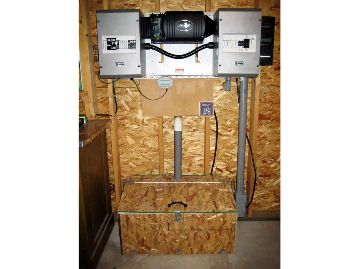
My system mainly consists of OutBack Power Systems equipment, including the inverter, breaker boxes, charge controller, and other components. You can buy these components at many different locations. A few online stores I recommend are Affordable Solar, the Alternative Energy Store, and The Solar Biz.

M14-Solar-system-schematic

Resources

Project Steps

1. Solar Panel Array

Solar PV systems normally consist of multiple solar panels connected together in series and/or parallel to form a solar PV array. A solar charge controller protects the batteries by regulating the current and voltage coming from the solar array; its specifications usually determine how the solar panels must be configured. For instance, some charge controllers only accept specific DC voltage inputs of 12V or 24V. Therefore, you can connect two 12V solar panels in series to create a 24V solar PV string. You can then combine multiple 24V strings in parallel and connect them to a PV combiner enclosure (which takes the input from multiple solar panels and combines them into one DC output).

Note that 24V is too low for certain system designs, because when you increase the current on a wire with only 24V, you decrease efficiency and increase voltage loss. A larger-gauge wire would offset power loss by reducing resistance, but the best solution is to use a charge controller that accepts a dynamic DC voltage and steps down the voltage to charge the battery bank. Dynamic charge controllers like the OutBack MX60 enable you to stack solar panels in series up to 150 VOC (open circuit voltage). This configuration allows multiple solar panel stacking options and saves money by reducing the wire size needed.

2. PV Combiner Enclosure

M014_pvcombiner2_r

M014_pvcombiner1_r

The OutBack PSPV combiner box combines multiple strings of solar panels together in parallel to form a solar array. Each string of input wire will have a specific voltage and amperage, depending on the solar array configuration. While it’s OK to have different amperage ratings on the input strings (because the amps get added after leaving the combiner box), you should not combine multiple strings of solar panels with different voltages. I have two 10-amp breakers in my combiner box
for my 2 strings of solar panels.

M014_pvcombiner1_cylindar

The gray cylinder is the DC lightning arrestor. Its 3 wires go to the positive bus, negative bus, and ground. It protects your equipment from lightning damage and is required by code.

3. Grounding Equipment

Proper equipment grounding is a must. It reduces and prevents shock, trips a breaker if a ground fault occurs, and limits the potential for equipment damage by lightning. Below the combiner box, I’ve driven an 8′ copper ground rod into the ground.

Underground, I connected a direct burial ground lug to a 6-gauge copper wire connected to the combiner box at the designated location. I screwed code-compliant ground lugs into each aluminum rail that touches a solar panel. A copper wire extends from these solar panel ground lugs to the ground rod below the combiner box. Read John Wiles’ article, “To Ground or Not to Ground: That Is Not the Question (in the USA).”

4. DC Disconnect Switch

M014_dcdisconnect2_r

How do I ground my power center inside my shop, route DC cable into my workshop, and easily disconnect the DC power source for safety? With Square D’s HU361RB 600V DC 30A unfusible disconnect switch. The cable entering the box from the bottom right is the solar input from the OutBack PSPV combiner. These wires connect to one side of the disconnect junction and to the ground bus. Three additional wires connect to the other side of the disconnect junction and the ground bus, then run into the building through the conduit. Check with your local inspector to see if PVC conduit on the DC side is allowed to enter the building.

M014_dcdisconnect1_r

Note the bare copper wire that’s connected to the ground bus bar, and then runs down the side of the building to connect to another 8′ ground rod. The NEC requires a separate ground rod for the AC side of the system, and these 2 grounds need to be bonded together. Again, check with your local inspector for details.

5. DC Breaker and Charge Controller

M014_flexwareDC500_MX60_r

The Flexware FX500 DC enclosure serves multiple purposes with room for expansion. The 3 wires that enter the building from the DC disconnect switch enter into this enclosure. The green wire connects to the ground bus bar. The black wire connects directly to the negative terminal of the solar charge controller. The red wire connects to one side of a 60A breaker. The other side of the breaker then connects to the positive terminal of the charge controller (black enclosure on the right of the photo). This breaker allows you to protect your solar charge controller, and disconnect the solar input when maintenance is required.

The sun’s input to your panels varies throughout the day — the sun will shine on the panels at one moment, and be covered by clouds the next. This up-and-down cycle would shorten a battery bank’s lifetime without a solar charge controller, which regulates the charge to the battery bank.

M014_insideDC500_1_r

The controller has 2 terminals that connect to the battery bank. The black wire from the charge controller’s negative terminal connects directly to the negative bus in the DC enclosure. The red positive wire on the charge controller connects to one side of a 60A breaker in the DC enclosure. (The other side of the breaker connects to the positive bus bar in the enclosure.) This additional breaker protects the charge controller on the battery side, and allows for charge controller isolation during maintenance.

M014_insideDC500_2_r

The enclosure’s negative bus bar is connected to a DC current shunt included with the FX500 DC enclosure. The shunt measures current and voltage. When used in conjunction with a battery meter, it can provide valuable information relating to your battery bank. The shunt connects to the negative end of the bank and to the negative side of the inverter.

Similar to the PSPV combiner box, I have another DC lightning arrestor in my FX500 DC enclosure box. You can never be too careful when it comes to protecting your expensive equipment. Connect the red wire of the lightning arrestor to the positive bus bar, black wire to the negative bus bar, and green wire to the ground bus bar.

If you have a roof-mounted solar array, then the NEC requires a Ground Fault Protection (GFP) device. This device disconnects the solar array when a ground fault is detected. For details on this and other grid-tie subjects, see John Wiles’ “Making the Utility Connection.”

6. Battery Bank

M014_batterybox2_r

My battery bank consists of four 6V Trojan T125 lead-acid batteries wired in series. Each battery has a 240 amp-hour rating at 6V, so the 4 batteries connected in series yield a power rating of 24V at 240Ah. This particular lead-acid battery is considered a “deep cycle” battery, which is different than a car battery because you can drain its energy capacity by up to 50% without damaging the battery.

The Trojan T125 battery requires adding distilled water on a regular basis, because charging and discharging consumes water and releases small amounts of hydrogen into the air. Since hydrogen is flammable, venting is required by code if you have a battery bank inside a house or workshop. I recommend reading “Battery Enclosures” from Home Power magazine #119 for details on how to build your own code-compliant battery enclosure.

Using three 10″ 4/0 gauge cables, I connected the positive terminals to the negative terminals of all 4 batteries. This series connection leaves open 1 positive and 1 negative terminal, to which the 72″ cables coming from the DC enclosure box connect.

7. Inverter

The components in a solar system must be carefully matched with the type of inverter you use. My inverter requires a 24V battery source. Many other items, such as inverter cable gauge, breaker ratings, solar charge controller voltage, and the solar panel configuration, are all tied to the inverter.

M014_inverter_r

One of the main features of the OutBack GVFX3524 inverter is that it can charge batteries as well as sell power back to the utility grid. I’m into electronics, and being able to utilize DC power for my electronics projects in addition to selling excess power back to the grid was my ultimate goal, which is why I chose the GVFX3524.

M014_insideinverter_r

Most grid-tie inverters don’t work with battery banks, which means they’re usually more efficient than off-grid inverters, because 10% of the electricity is lost when charging a battery (and further losses occur when inverting DC power to AC). However, grid-tie inverters that don’t use batteries require a DC input voltage as high as 150V to 250V. This high voltage requires a lot of solar panels wired in series to meet the minimum voltage. Because I didn’t want to buy or build nine 24V solar panels, I decided to use the OutBack inverter instead of a typical grid-tie inverter.

8. AC Brealer Enclosure

M014_FlexwareAC500_3_r

An OutBack AC enclosure connects the inverter to various AC loads in my workshop. Any standard AC breaker box would work, but the OutBack AC enclosure has punch-out holes that line up perfectly with the inverter, so no wires are exposed between the 2 units.

OutBack makes an input/output bypass (IOB) assembly kit designed to work with the AC breaker enclosure, specifically for grid-tie scenarios. A bypass assembly kit is a set of breakers that can be used to isolate your inverter from the grid when maintenance is required. The AC loads that the inverter normally powers through separate breakers get switched to being powered by the grid. You can see the black bypass plate and set of breakers in the above photo.

9. Grid Connection

One of the most difficult parts of this project is configuring the solar PV system to sell power back to the grid. It can be beyond the realm of some solar installers and electricians alike. You must contact your electrical utility company to obtain permission to connect to the grid, and figure out what needs to be done to receive any available financial incentives, rebates, and tax credits. I also recommend showing your plans to a licensed electrical inspector, who can tell you what you need to do to pass inspection.

Following are a few things I learned while working with the local electrical inspectors. When digging a trench from one building to another, the trench must be 2′ deep. Grey PVC pipe can be Schedule 40 underground but must be Schedule 80 above ground. Conduit expansion joints must be used with trenched conduit in cold climates above ground level, to prevent the conduit from cracking from temperature changes. All AC cable runs are required to have an AC disconnect at the point of entry to any building. This disconnect can be inside or outside of the building.

M014_pointofentrydisconnect_r

I’m using another small load center to meet the National Electrical Code’s point-of-entry disconnect requirement. You can see the black wire, which runs to the AC In bus bar in the Flexware AC500 box.

Connecting to the utility grid has been one of the most confusing parts of the whole process. The NEC 2005 code has specific requirements that regulate the amperage load on the load center’s bus bar and conductors. See makezine.com/go/nec for details on the NEC 2005 Residential Utility Connection options and requirements. Again, see “Making the Utility Connection.”

10. AC Disconnect

M014_ACDisconnect_r

My local electric utility requires an AC disconnect switch on the outside of my workshop or house before connecting to the grid. You can use Square D’s DU221RB 30A 120/240V AC 2-pole disconnect switch on the outside of your house or shop before connecting to the main AC load panel.

11. Optional Accessories

M014_trimetric_r

Other items I’m using in my power center are the Trimetric 2020 battery meter (above), and the OutBack Mate remote monitor/control and temperature sensor (below). The Trimetric 2020 is primarily for monitoring battery conditions including voltage, charge percentage, amps in or out of the battery bank, and total amp-hours used; it connects to the DC shunt inside the Flexware FX500 DC enclosure box. The OutBack Mate is used to control and program the OutBack inverter, via a standard Cat 5e network cable.

M014_mate_r

12. Wire Information

The type and size of wire that you use throughout your solar installation is very important. An excellent wire efficiency/voltage drop spreadsheet for copper wire is available here.

I’m using 6 AWG THHN wire throughout the DC and AC enclosures. I’m using 6 AWG THWN wire in wet locations, where conduit is used outside. The ground wire should be either 6 or 4 AWG bare or stranded copper. Throughout the inside of the workshop, I’m using Romex 12/2 for 20A AC circuits, and 14/2 for 15A AC circuits. The battery and inverter cables are 4/0 AWG copper wire.

13. Off-Grid vs. Grid-Tie

If you live in a rural area outside the range of the utility grid, the electric company could charge you $20,000 or more to run an electrical line to your property. So you could either spend the $20,000 to connect to the grid and pay a monthly electricity bill, or invest it in clean solar PV technology and reduce or eliminate your monthly bill.

However, an off-grid home requires a substantial (and therefore costly) battery bank with enough capacity to power the home for extended days without sunshine.

A grid-tie system is cheaper because you don’t need to buy and maintain a large set of expensive batteries. When sending power back to the grid, you will offset your current electrical usage, and if your solar electricity production surpasses your usage, your utility meter will spin backward. At this point you’ll be selling power back to the utility company.