YouTube player

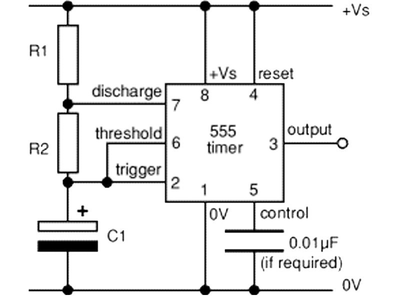
With an estimated one billion 555 timers manufactured annually, you know this component must be versatile! We’re going to learn how to build and control drivers for three very different types of motors using a breadboard, resistors, diodes, transistors, and some 555 timers (along with a sprinkling of CMOS logic). These motor drivers are the basis of many robotics and other motor-control applications.

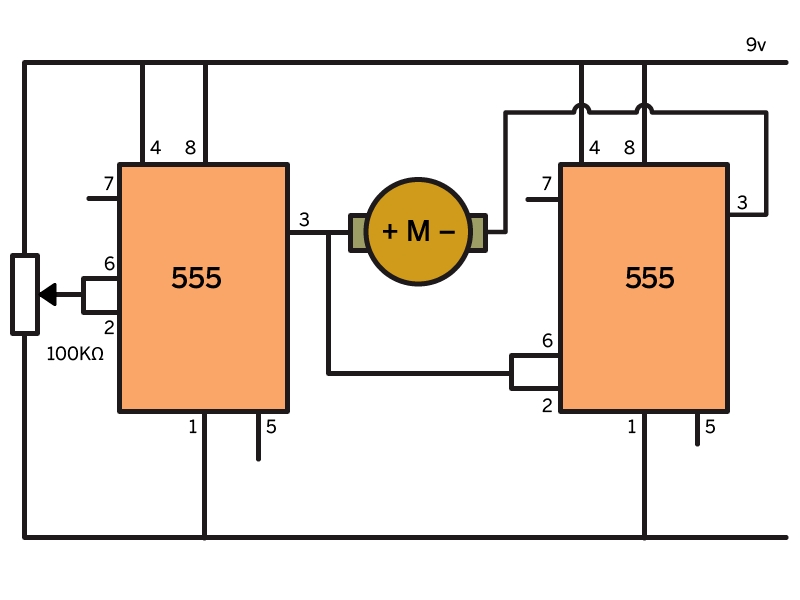
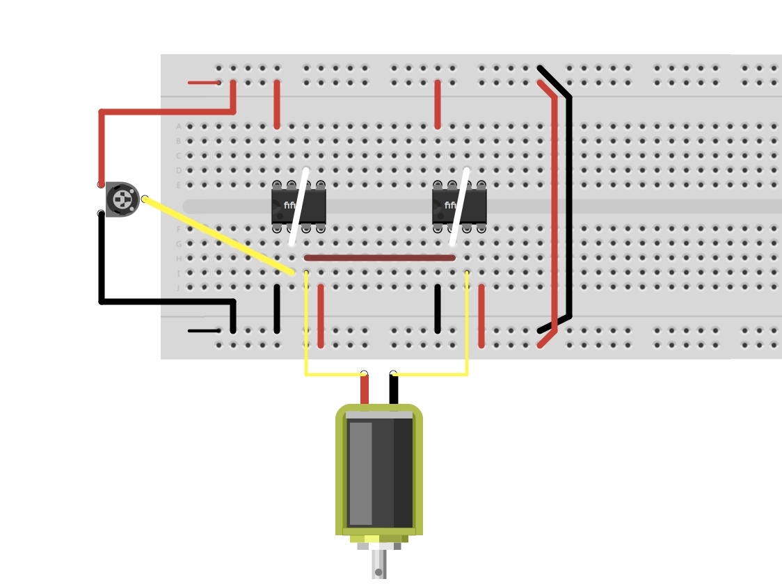
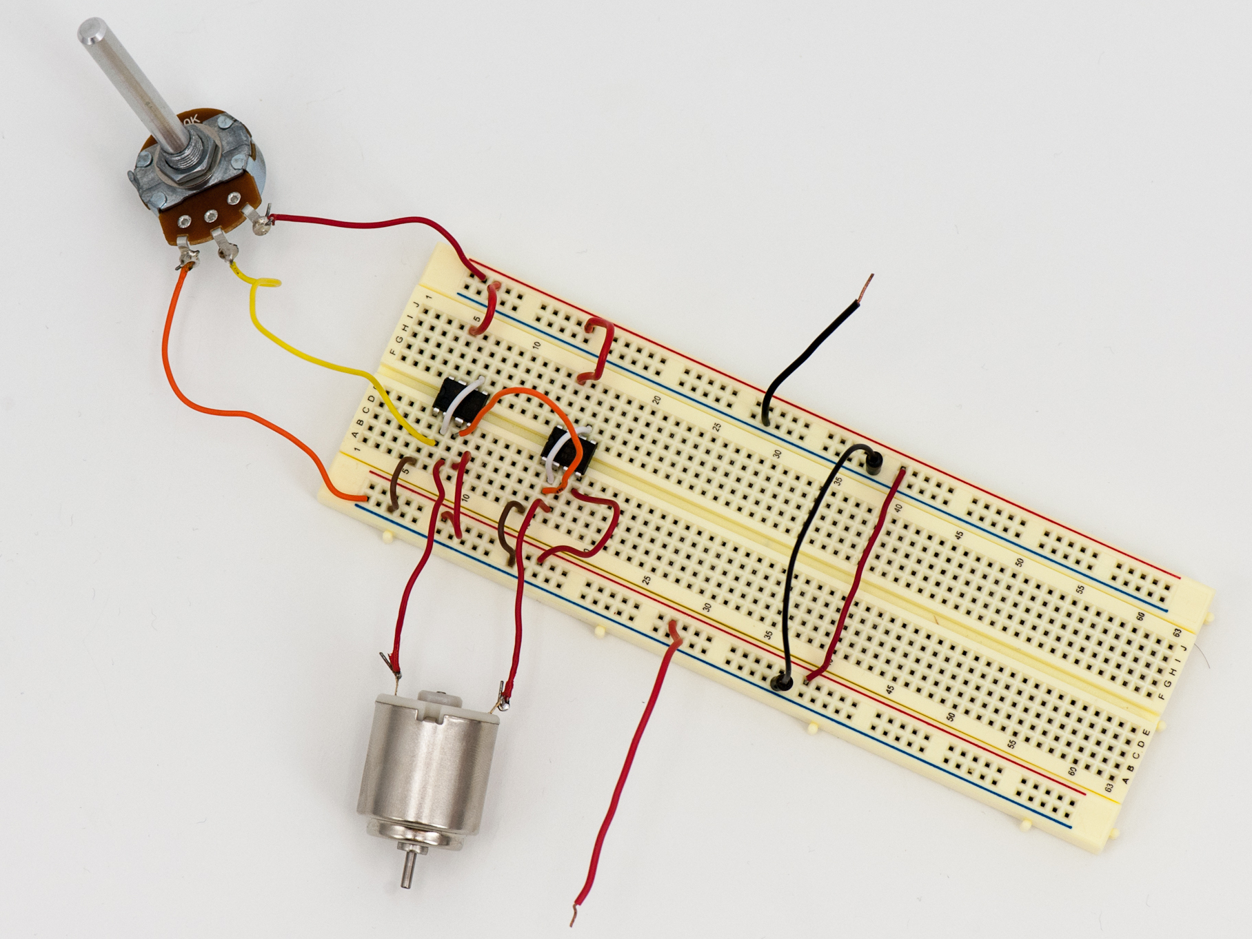
The first project is one of the simplest “H-bridge” circuit designs around. It consists of only two 555 timers, a potentiometer, and some hookup wire on your breadboard.

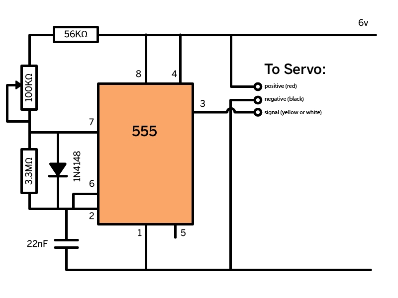
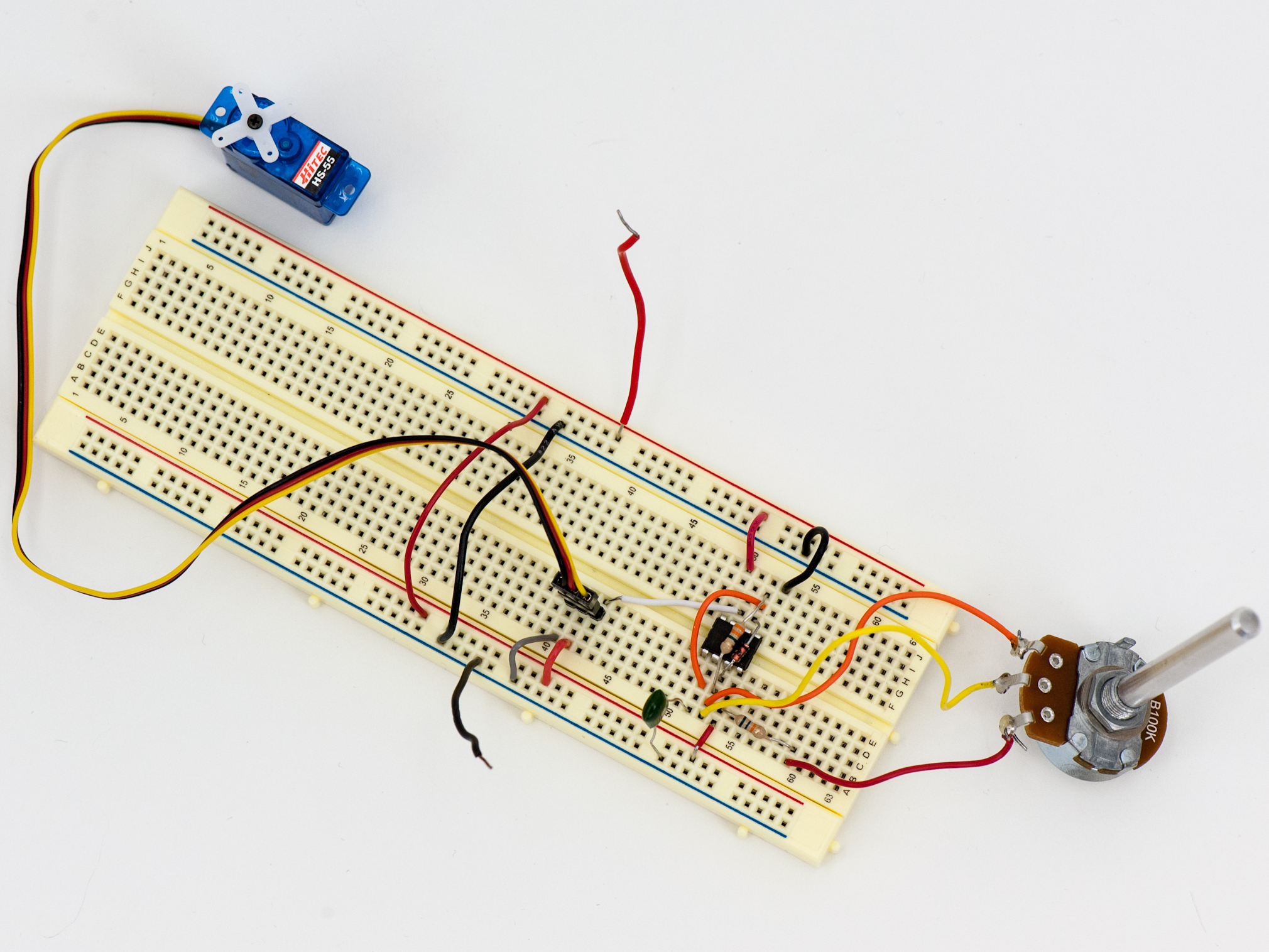
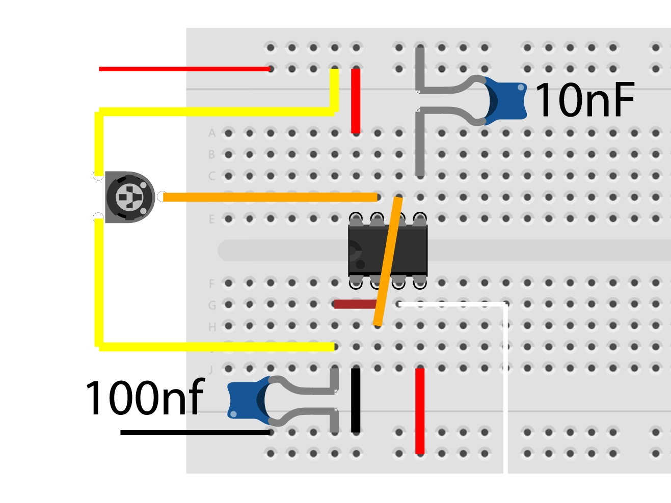
In the second project, we will build a servomotor controller using only one 555 chip and a small assortment of other parts. Servos often act as the “muscle” of a robot.

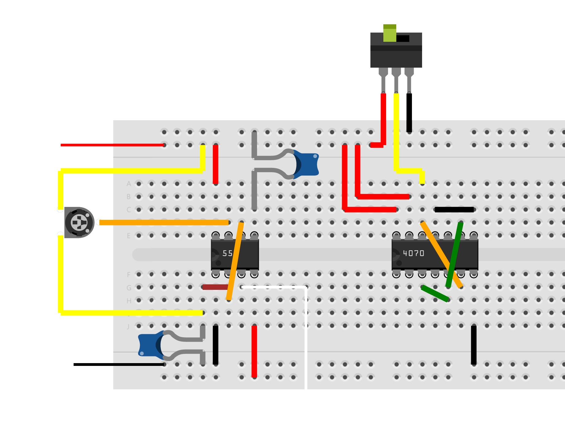
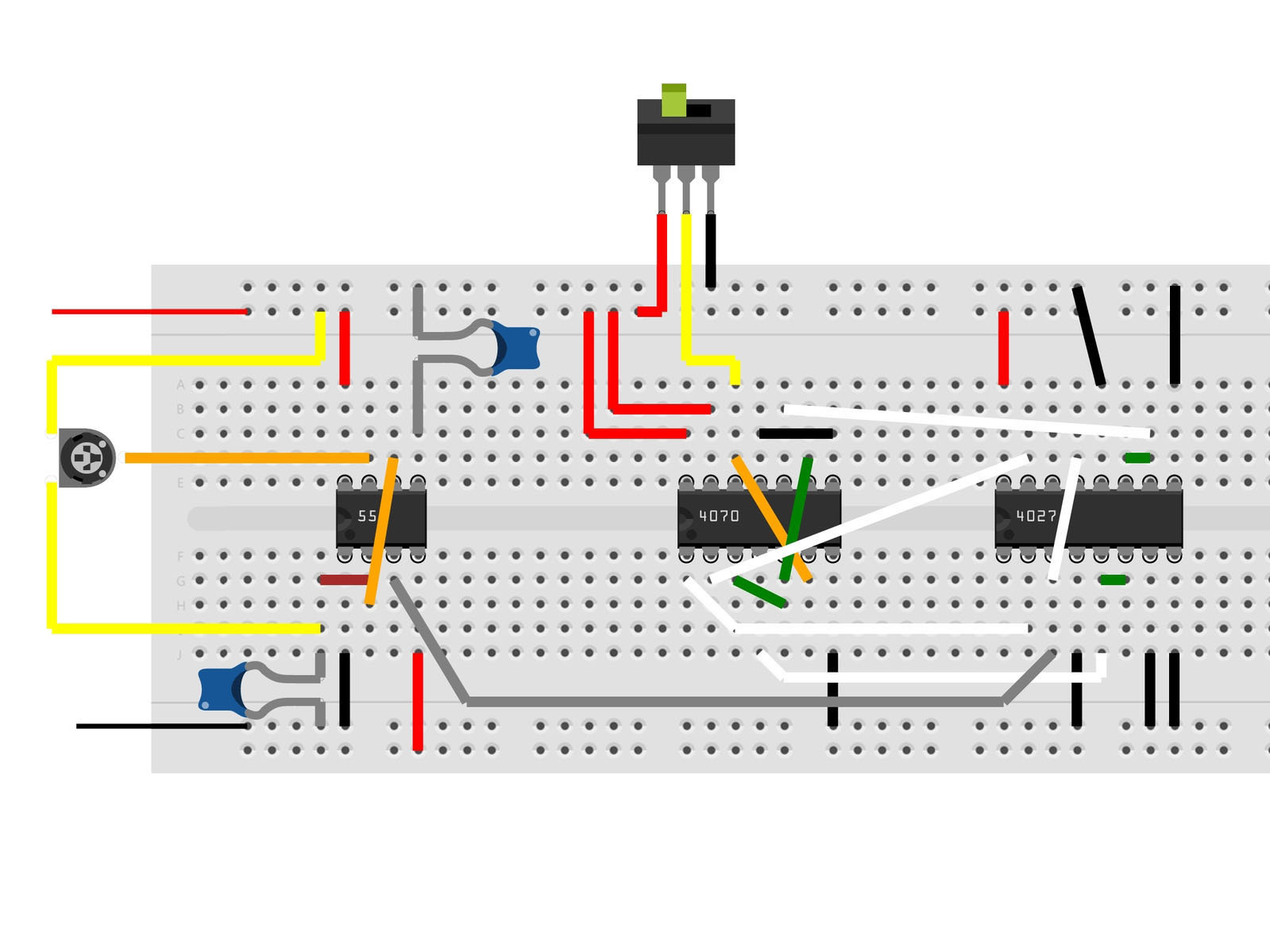
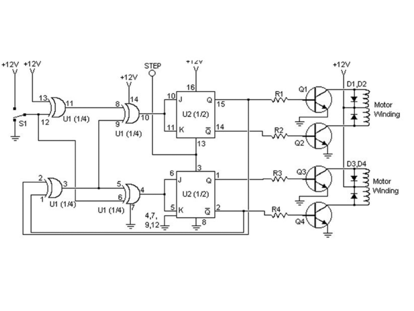
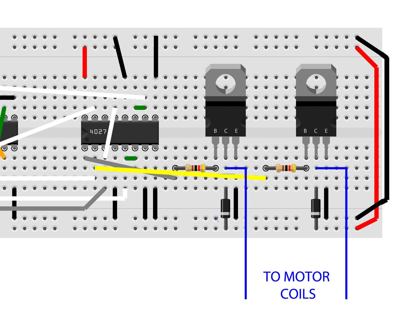
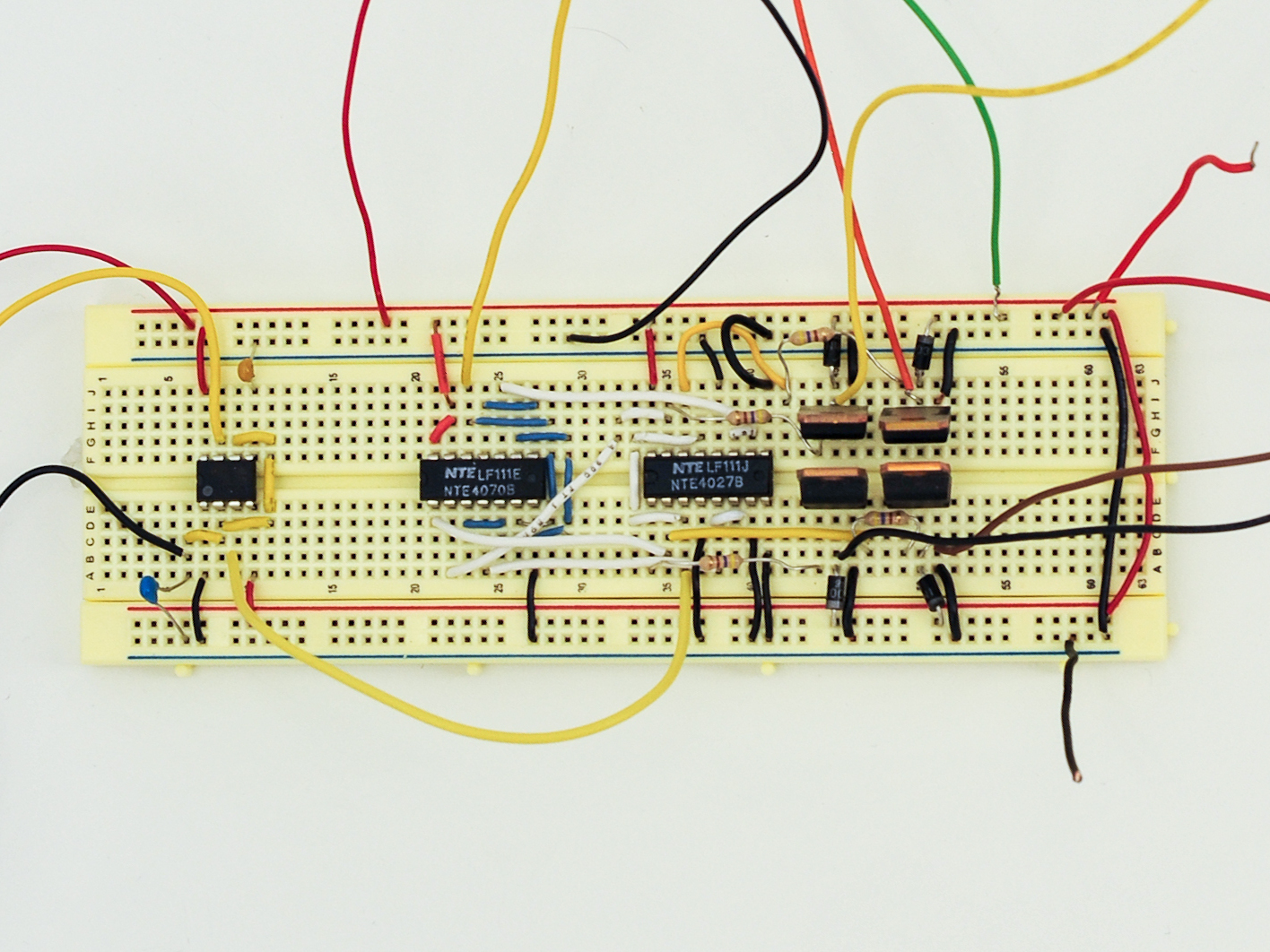
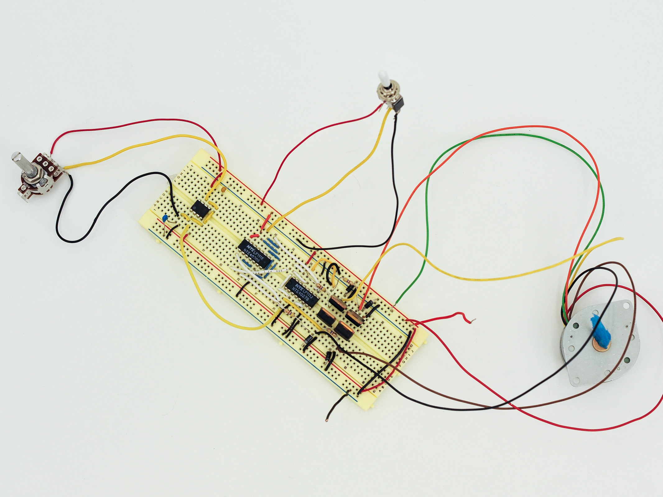
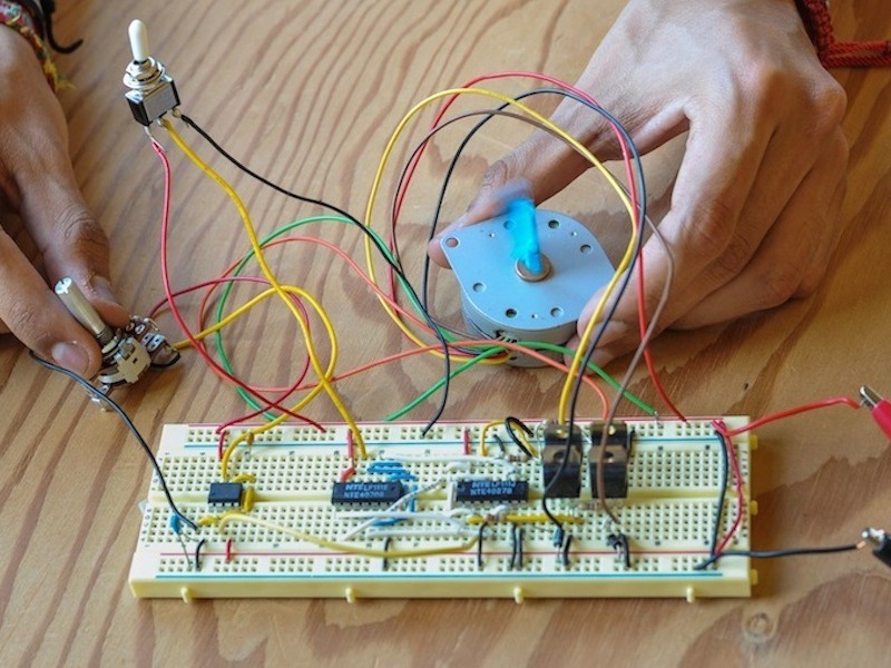
And finally, for the the third project, explained over three steps, we will build a simple stepper controller. This project will introduce you to the XOR logic gate (pronounced “Eks-Or”). Regarded as exclusive or, the output is true only if gate one or gate two are true; if both gates are true or both gates are false, the output is false.

Project Steps

Project #1: 555 H-Bridge Motor Driver

This is a clever idea: using two 555 timers, you can create a simple H-bridge motor driver for controlling DC motors. An H-bridge is the basis of many robotic drive systems, as it lets you easily control the direction of a motor. Twisting the potentiometer will turn the DC motor one direction, then twisting it the other way will turn the motor in the other direction.

The circuit works by getting the output to source and then sinking the current. 555 timers can do this with up to 200ma, more than enough to drive a small DC motor. The two 555 timers work in an opposite configuration: when one sources, the other sinks, and vice versa.

This particular circuit has a very small component count too – just two 555 timers, a potentiometer, and hookup wire. (Original circuit diagram from 555-Timer-Circuits.com)

Once completed, hook up 5v to the power rails on the breadboard (the red and black wires on the left of the breadboard diagram).

To power all three of these circuits, you’ll need to deliver voltages from 5-6v to 12v. We recommend either using a benchtop power supply or a variable-voltage power supply.

Project #2: Controlling a Servomotor

Now we’re going to control a servomotor. This is a special kind of motor, often used as the “muscles” of a robot. A servomotor takes a stream of pulses, where the width of each pulse controls the absolute position of the servo. This allows for precise positioning of motor turns.

To do this, we’re going to use a 555 timer in “Astable” mode – this will run it as an oscillator. Our 100K potentiometer can be used to control the width of the pulses and so control the position of the motor. (Original circuit diagram from 555-Timer-Circuits.com)

To build this circuit, we’re going to need one of our 555 chips, a 5v hobby servomotor, a 3.3MΩ resistor, a 56KΩ resistor, a diode (1N4148), and a 0.022μF capacitor.

In this guide we’ve included breadboard illustrations along with photographs. Hopefully this should make the circuit clearer and easier for you to follow. Lay down the connections as shown. Note the orientation of the diode – it only works one way!

Connect 5-6v DC to the red and black wires on the left of the board and you’re good to go. If you’ve done everything right, you should be able to move the servo by turning the potentiometer!

Note: In practice, this simple servo motor controller might prove to be a little “jittery.” That’s because the variable PWM is not entirely stable. I have found that better quality servomotors are quite effective at filtering out the instability.

Project #3: Super-Simple Stepper Controller

OK, now for the big project! A stepper motors is a special type of motor that only moves very slightly each time a combination of voltages is applied to its input pins. To make a motor like this turn, we have to sequence a set of voltages to appear on the correct pins at the correct times. This is a tough assignment, so our trusty 555 timer is going to need a little help!

That help is going to come from a couple of CMOS logic chips: A 4070 Quad XOR Gate, and a 4027 Dual JK Flip-Flop. Our 555 timer is going to generate the stream of clock pulses to govern the speed of the motor. Then our logic gates will sequence the signals into the correct order to make the motor turn.

This project will hook up to a Unipolar stepper motor — one that typically has 6 input connections.

Let’s start by building a simple 555 timer in astable oscillator mode. For this we’re going to need a 555 timer, a capacitor and potentiometer. (Original circuit from www.kpsec.freeuk.com/555timer.htm) In the schematic, the capacitors are simple ceramic caps (these are unpolarized, so they can be inserted either way around).

The resistors at R1 and R2 will be substituted with the potentiometer.

Hook up 12v and check the output (white wire) with a frequency counter to see if you are getting a stable square wave oscillation. Turning the potentiometer should change the frequency. Note: although not pictured, as with the previous layouts, I have connected the upper and lower power rails of the breadboard together with jumper wire.

Project #3: Super-Simple Stepper Controller (continued)

Once we have the oscillator, err… oscillating, the next step is to hook up the 4070 XOR Gate and SPDT switch. Follow the connections in the first diagram; add the SPDT switch first, then add the chip.

Next up is the 4027 chip. This is shown in the second layout diagram.

Note: in the circuit diagram, R1-R4 are all 1KΩ (brown-black-red) resistors; Q1-Q4 are TIP3055, TIP31, or any suitable NPN power resistor. Diodes are all 1N4003. Placing these will be our next step.

Project #3: Super Simple Stepper Controller (continued)

Finally, we have to add the 4 transistors and protection diodes. For clarity I’ve shown the first two hookups. The grey and yellow wires run to the 470Ω resistors, and the blue output wires run to the coils of the motor.

Replicate the transistor/diode hookups using outputs 15 and 14 from the 4027 chip. See the accompanying photos for component placement.

Finally we need to connect the common of the stepper motor connections to +12v. When the transistors are activated, the current will flow from the common line, through the motor coil, and to ground via the transistor.

The diodes are there to protect the transistors from EMF back-surges.

Conclusion

As you can see, the 555 timer is a really great component. It was introduced in 1971 by Signetics - and it's still just as useful today - with over 1 billion units produced annually.