thing

Webcams are a fun and useful tool. Being able to control where they’re looking remotely, though, takes their usefulness to a whole new level. Whether you’re watching your pets while you’re away or allowing friends to participate in an event from the other side of the world, a web-enabled remote servo camera puts the end user in control of the experience.

Put a Pi on the Web

The Raspberry Pi provides a perfect base platform for creating internet-connected devices. When researching how I was going to connect my device to the web, I ran into Make:’s very own Matt Richardson’s post describing how to use the Flask framework to easily create projects for the web on the Raspberry Pi. Flask allows you to take your existing Python apps (the preferred language for developing applications on the Raspberry Pi) and add in an HTML template to provide a web-page interface for the end user. In this project I provide an HTML template document that’s pretty bare-bones, so it’s easily understood by anyone who wants to look under the hood and also provides a good starting point if you want to customize it for yourself.

Stream Video from the Pi

The next tool needed was a way to send video from the Pi across the web. When using a less powerful system like the Pi, every little bit counts, and the real-time compression and streaming of video can be a huge drain on a system. After trying a couple of different options I opted to use MJPG-Streamer. The performance from MJPG-Streamer was hands-down the best of any service I tried on the Raspberry Pi.

Control the Servomotors

Finally I needed a way to control the servos for the pan/tilt mechanism. The standard library on the Pi for accessing the I/O pins is called GPIO. While GPIO makes it easy to do basic actions, its software-based PWM system is very inaccurate and temperamental for controlling servomotors. After running into problems and having a few friends review my code to ensure I wasn’t going mad, I decided to abandon GPIO in search of a better solution. The winner was an alternative to GPIO called RPIO. With RPIO, I had access to a semi-hardware driven PWM signal. This final piece brought it all together into a fully functional project and a great starting point for connecting your world to the web!

All the code for this project can be downloaded from Github and the 3D models from Thingiverse.


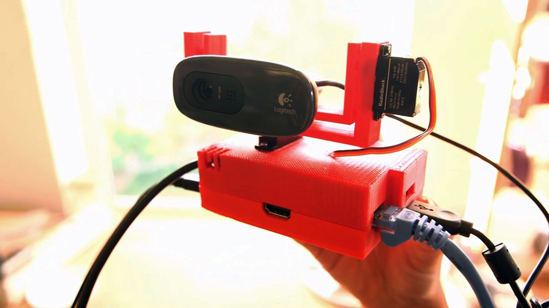
NOTE: eLinux has a list of Pi-compatible USB webcams. This project was built using the C260 webcam, which may no longer be available. The C525 reportedly “works fine without powered hub” but was un-tested with our design. The C270 reportedly “works fine with external power” in the form of a powered USB hub. The 3D design files are for the C260/270 but the premise for the design can be modified for the webcam of your choice.

Project Steps

Flash the SD card.

The OS for this project is Raspbian, a Linux OS built especially for the Raspberry Pi. Most of the default settings are still in place including the password (raspberry). After you complete all of the installation pieces, you should log into the system and run raspi-config and change your password and set any other settings you might wish to change (time zone, keyboard settings, etc.).

There is a lot of configuration needed to the Raspbian image to make this project work. To make things easier I have prepared the OS ready to go — all you need to do is download the PiCam image from http://cdn.makezine.com/make/WeekendProjects/HomeSentrySecurityCamera/PiCam.img and flash it to your SD card.

Flashing the image could be an article just in and of itself — every time I play with a Pi, there is a a new and easier way to do it. For this project, follow the guide from the Raspberry Pi Foundation at http://elinux.org/RPi_Easy_SD_Card_Setup. I’m running a Mac, so I used the very simple ApplePi-Baker app and it was easy as well … pie.

Make (or buy) the 3D-printed case.

To house the Pi and create a base for the pan/tilt mechanism, I designed a special 3D-printable case. It’s based on a design from Thingiverse user Josh Campbell. You can download it and print it yourself from http://www.thingiverse.com/thing:274468.

If you print the model yourself, the smaller of the 2 pan/tilt arms will need to be printed with support material to allow the support arm to be printed correctly.

If you don’t have access to a 3D printer (and I bet if you try hard enough you do) then you can buy the case, printed for you by Shapeways, here: https://www.shapeways.com/model/1792280/raspberry-pi-case-with-servo-pan-tilt.html?li=shop-inventory&materialId=6

Prepare the servo power cable.

Start by cutting off the small, Micro-B end from one of your 2 USB cables. (Leave the other intact.)

Strip 1″ of the outer insulation and you’ll find 4 wires inside (black, red, white, and green).

Strip about 1/4″ of insulation from the black and red wires. Using a multimeter, verify that these are your power and ground wires.

Trim away the cable shielding and cut the white and green wires flush with end of the main cable insulation.

Soldering the cable.

Cut 3 lengths of heat-shrink tubing: 1/2″ (1) and 3/8″ (2).

From your jumper wire kit, take out the row of headers and snap off 2 sets of 2 headers.

Slide the 1/2″ section of heat-shrink over all the wires and down the USB cable a few inches. You want to make sure it doesn’t get heated up while you’re soldering.

Carefully wrap the bare end of the red wire around the short ends of both pins on one of your 2-pin headers.

Solder the wire in place, ensuring it’s firmly connected to both pins.

Do the same thing with the black wire, wrapping and soldering it to both pins of your second 2-pin header.

Place one 3/8″ section of heat-shrink tubing over each set of headers and slide them down to cover your solder joints. Slide the 1/2″ section of heat-shrink up so it covers the white and green wires you trimmed off earlier.

Using your soldering iron or preferably a heat gun, warm the heat-shrink tubing to seal it in place.

Mount the pan motor.

Run the servo cable from one of your servos down into the large rectangular hole on the top of the project case, and try to push the servo into place. There’s a wide spot where the halves of the servo body are joined; if it gets stuck, use a small file or sandpaper to slightly open the hole on the top of the project case until you can fully insert the servo.

When the servo is pushed all the way in, use a screwdriver to tighten the 2 long mounting screws that were included with your motor.

Add the tilt motor.

Run the connector from the second servomotor through the small rectangular hole in the top of the case. Both servo cables should now be run into the inside of the case.

Don’t mount this servo yet.

Wire the motors.

Run the jumper ends of the cable you built through the circular hole on the back of the case top.

Plug the black header pins into both servo connectors, into the holes matching the brown wire from each servo.

Plug the red header pins into the center connector hole on both servo connectors, matching the orange wires.

Finally, get 2 purple jumper wires from your jumper wire kit and plug one into each the remaining holes on the servo connectors, matching the yellow wires.

Attach the tilt motor.

Push the tilt servo into the servo-shaped hole on the larger of the 2 printed arms. It should be a tight fit, but you might need to clean the hole a little with the file or sandpaper if there’s too much drooping from the overhands.

Screw the motor into place with the 2 long bundled screws.

Connect the servos to the Pi.

The 2 purple jumper wires that you connected to the servos need to be plugged into the Raspberry Pi. These are the control wires that will send the signal to change the servos position.

The signal wire from the pan motor (the one attached to the project case) will plug into I/O pin 23. That’s the 8th pin down on the outside of the I/O connectors.

The signal wire from the tilt motor is plugged into I/O pin 22. This is the 8th pin down on the inside row.

Power it up.

It’s time to plug everything in for the first time. Slot your formatted SD card into your Pi. Plug in your Ethernet cable from your network. Since this is your first time booting up it might be useful to also plug in a USB keyboard, mouse, and a HDMI monitor.

Plug both USB cables into the dual-port USB charger and plug the unmodified USB cable into the back of your Pi beside the SD card. Your Pi should now boot up.

Zero the servos.

To connect to the Pi remotely, you’ll use the SSH utility built into Mac and Linux. (If you are a Windows user, you can use Putty as an SSH client. Hey Microsoft, get us native SSH!)

From a terminal window type in:

ssh pi@picam

and hit Return. If you can’t connect, try to ping picam. If you receive the error message ping: cannot resolve picam: Unknown host then use your monitor and keyboard to find your IP address (use the ifconfig utility) and then connect by using the IP address like this: ssh pi@192.168.1.10.

Once you’re connected, change your directory to picam with:

cd picam

Run the picam.py Python script as root:

sudo python picam.py

You should see the output:

Using hardware: PWM

PW increments: 10us

Initializing channel 0...

add_channel_pulse: channel=0, gpio=23, start=0, width=154

init_gpio 23

add_channel_pulse: channel=0, gpio=22, start=0, width=154

init_gpio 22

* Running on http://0.0.0.0:80/

After starting the script you should hear both of the servos move into their starting position.

Hit Ctrl+C to terminate the program. When you’re back at the terminal prompt, type:

sudo shutdown -h now

to shutdown your pi. Once the shutdown is complete usually about 30 seconds, be sure to unplug your power cables before continuing.

Attach the servo arms.

Now that the servos are zeroed, you can attach the arms to them. Start with the larger, pan arm. Place it so the long side of the arm is running parallel with the long side of the case and the servo motor, on the same side as the USB and Ethernet ports on the Pi. Press the pan arm down onto the servo gear then screw it into place with the small screw.

Run your zip tie through the bottom holes of the tilt arm. The ends should be facing up and not zipped together yet.

Angle the tilt arm so you can push the axle on the end of the arm into the hole in the pan arm. Once in, you should be able to press the tilt arm onto the servo gear on the pan arm. Screw it into place with the remaining small screw.

Attach the camera.

Place the camera on on the arm and secure it by tightening down the zip tie. Make sure you pull it down tightly so the zip tie doesn’t hit the screw head or arm bellow.

Plug the camera into one of the Raspberry Pi’s USB ports and plug your SD card, network, and power cords back in.

Launch the camera.

Once your Pi has booted back up, SSH into it again.

This time you’ll start the camera! First move to the folder containing the program you’ll use to stream the video. From your terminal prompt type:

cd ./mjpg-streamer/mjpg-streamer

Now launch mjpg-streamer with the command:

./mjpg_streamer -i "./input_uvc.so" -o "./output_http.so -w ./www" &

You’ll see some errors but these are related to unused modules. Your Camera light should turn green and at the end of your output you should see:

o: www-folder-path...: ./www/

o: HTTP TCP port.....: 8080

o: username:password.: disabled

o: commands..........: enabled

Now you can use the Ctrl+C keys to get back to the terminal prompt. Type cd and Enter to return to the root directory.

Wrap it up.

Now that all the systems are assembled and working, it’s time to bring it all together.

From your terminal, move back to the picam directory:

cd picam

and launch the PiCam app:

sudo python picam.py

Once the app has launched, open your browser (we’ve tested this in Chrome and Firefox) and go to: http://picam/

You should now see the output from your camera and control buttons to move the camera’s view. Each button press moves the camera 10º.

To access the camera from the outside world, you can setup port forwarding on your router (every router is different, so look up instructions for yours). If you do, you’ll need to open 2 ports to redirect to port 80 for the page and 8080 for the video. For more information on port forwarding and running your own server on your Pi, check out this article from RaspberryWebServer.com.

Conclusion

The "Raspberry Eye" Remote Servo Cam will get you started with a basic snooping using your Pi, but there's a lot more you can do to extend the features. You can add WiFi, create a custom enclosure for outdoor deployment, or even increase your stealth by concealing the project in a common household object like a cereal box or a book.

For those not satisfied with the local network limitation on accessing the Raspberry Eye Remote Servocam, you can set up port forwarding and expose your project to the internet. However, be aware that there are no security or access control steps taken in the project — you're on your own for securing your Servocam.

Regardless of how you decide to hack your project, we want to hear about it in the comments below.