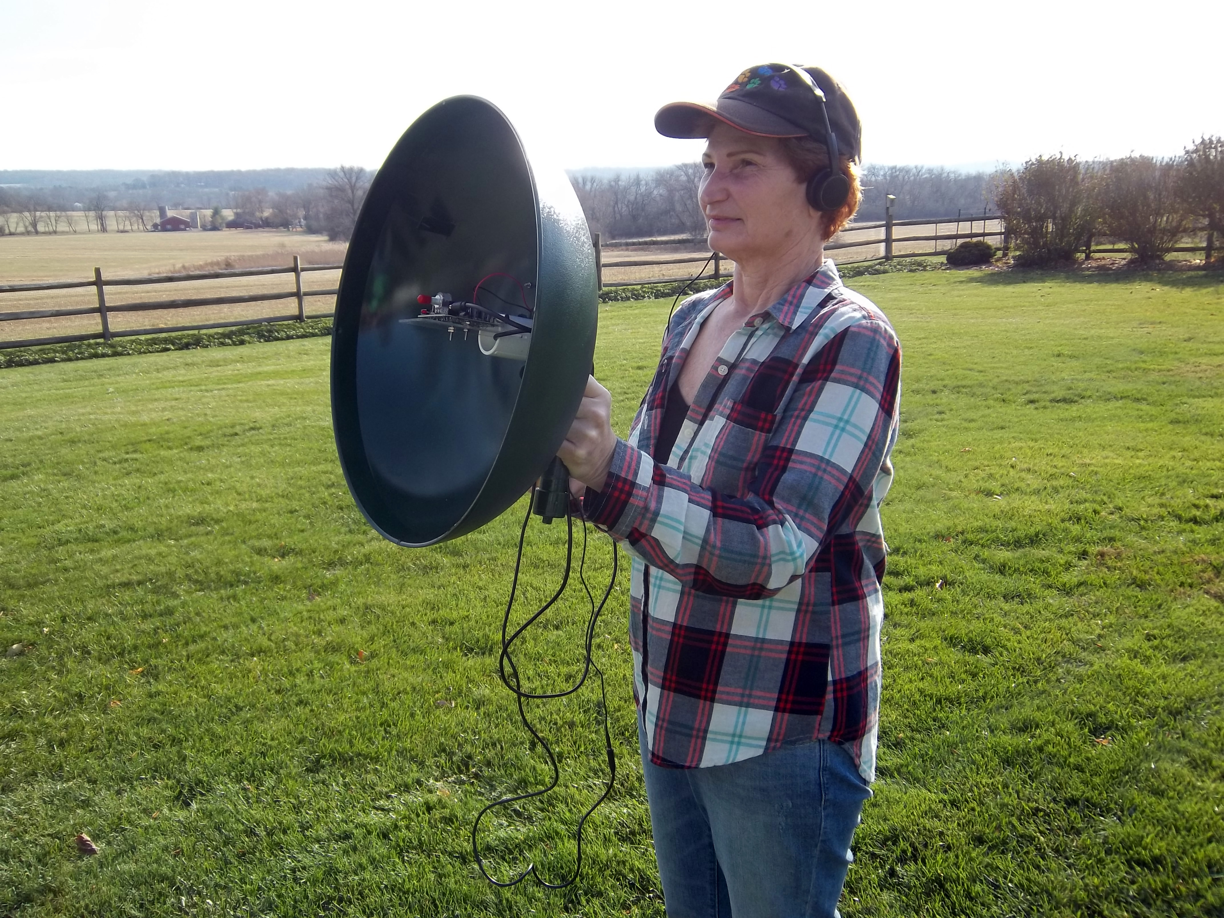
figure-4a

If you want to listen to faint sounds far away, you’re going to need a bigger ear. Parabolic microphones gather and focus sound waves the way a satellite dish focuses radio waves, making it possible to listen to the quietest of sounds hundreds of feet away. Parabolic mics are popular with nature lovers for recording birdsongs and other wildlife, and they’re great for eavesdropping on players’ chatter on the sports field. With this project, you can selectively amplify distant sounds and transmit them wirelessly to any FM radio. If you go further and capture the FM signal on your computer, you can even discover characteristics within the noise not possible to hear with unaided ears.

[youtube https://www.youtube.com/watch?v=pOxmdVWbmDE]

In addition to building the parabolic dish and PVC handle, you’ll need to assemble a stereo amplification kit, which requires through-hole soldering skill. This kit is not too difficult for beginners. Read the instructions carefully and use plenty of patience as you solder.

Project Origin

So what’s a squirrel baffle? It’s basically a big upside-down bowl that prevents rodents from climbing a pole and stealing food from a bird feeder. Repurposing a squirrel baffle as a parabolic dish is not an original idea. I owe inspiration to a video by Phillip Brummet. (Prior to watching his video, I had tried several different parabolic shapes — from salad bowls to 30″ satellite dishes.)

After testing several microphone options, I found that using a Velleman kit — which included both miniature microphones and an amplifier on a small circuit board — was the most robust and efficient solution.

Additionally, I combed old RadioShack catalog archives and found a “Big Ear” parabolic mic in the 1963 catalog.

1963-Radio-Shack-ad

These were also commonly advertised in the back of Silver Age comic books along with novelty x-ray specs and real live monkeys and dogs that fit into a tea cup!

Adding a Wireless Transmitter

After building the parabolic dish microphone, my next step was to wirelessly transmit sounds captured by the dish for remote listening. That’s where this design distinguishes itself — it’s unique in that you can monitor sounds from a distance without being tethered to the dish. Instead you can listen in via a simple FM radio (or even several radios). Surprisingly, commercially produced dishes don’t have this feature. The idea of using a wireless transmitter in tandem with a parabolic dish makes a lot of sense — you can tune out unwanted noise, and tune more directly into nature.

Squirrel baffle repurposed as a parabolic listening station.

9912haying

Here’s a view from my house deck, facing the Sourland Mountains. After a recent snowfall I used the Squirrel-Baffle Spy Microphone to listen in on geese some distance away, and was even able to hear the sound of snow melting:


Here’s how to build it.

What will the next generation of Make: look like? We’re inviting you to shape the future by investing in Make:. By becoming an investor, you help decide what’s next. The future of Make: is in your hands. Learn More.

Project Steps

Build the PVC handle

Cut a 4″ length of ¾” PVC pipe using cutters or a saw.

NOTE: The PVC length is not critical, you want it long enough to grip with your hand comfortably when you’re holding the parabolic dish. On the other hand (pun intended), don’t cut it too long or it will be top-heavy when mounted on a tripod.

Lay out all the PVC parts and the ¼”–20 × 7/8″ coupling nut. The nut will be used to mount the parabolic mic to a standard threaded tripod.

Dry-fit the PVC parts using minimal pressure and test that the pipe fits comfortably in your hand. You don’t need to test-fit the coupling nut.

Prepare the coupling nut

Mark the center of the ¾” PVC end cap. Most flat-bottomed PVC caps have a dimple in the center, which is an excellent point of reference.

Drill a 1/8″ pilot hole, then drill a 7/16″ hole using the pilot hole as a guide.

Test-fit the ¼”–20 × 7/8″ coupling nut into the 7/16″ hole you drilled.

Attach the coupling nut to the PVC cap

Lightly sand around the 7/16″ hole to roughen the surface and allow for better adhesion of epoxy.

Glue the ¼”–20 × 7/8″ coupling nut into the 7/16″ hole using 2-part epoxy. This bond has to be strong.

TIP: To hold the coupling nut in place while the epoxy is curing, create a jig by placing a small ball of aluminum foil on the workbench. Then place the PVC cap over the foil ball and seat the nut so that half of it juts out of the top of the cap. Double-check that the nut is square to the PVC cap.

Now glue the PVC coupling, 4″ pipe, and cap together using any suitable PVC adhesive.

CAUTION: PVC adhesives are extremely flammable. Pay attention to the product labeling for safe usage and appropriate drying time.

Connect PVC handle to the squirrel baffle

Lightly sand the outer edge of the squirrel baffle hole and the inside surface where it will mate with the 90° PVC elbow.

Test-fit the 90° elbow into the baffle hole to verify that it sits level, then glue it in place. Be sure to allow ample time to cure.

Now glue your PVC handle into the 90° elbow. Make certain the pipe is firmly pushed into the elbow and fits straight.

Drill hole for the audio cable

With a pen, mark the 90° elbow 7/8″ below the bend and roughly centered.

Drill a 1/8″ pilot hole at your mark, then widen it to 3/8″. Sand the hole to remove any burrs, then test-fit the 3mm audio cable.

Prepare PVC for mounting the Velleman kit

On the unthreaded side of the female PVC adapter, use a straightedge to mark both sides of the opening, centered across the pipe’s diameter.

Clamp the adapter in a vise and use a keyhole saw to cut 1″-deep slots on your marks. Use sandpaper or an emery board to smooth any rough edges.

NOTE: I used a keyhole saw because it removes enough material to accommodate a printed circuit board.

Foam spacer

Cut a 5″×½” strip of foam, which will serve as a soft spacer.

Press the foam into the round groove of the PVC elbow, inside the dish.

Running the audio cable

Gently screw the PVC female adapter onto the elbow inside the dish — don’t overtighten.

Feed the 3mm male end of the audio cable through the 3/8″ hole in the elbow. Pull the jack through to the inside of the dish.

Build the Velleman Super Stereo Ear Kit

The Velleman kit takes about an hour to assemble. Do not solder the battery pack to the PCB as shown in the kit instructions. The reason for this is that you’ll be mounting the battery pack on the handle of the parabolic dish, not the underside of the PCB.

NOTE: The red plastic tip on the volume pot in the image is not included in the kit; I had this red tip in my junk box and thought it was a nice touch!

Paint your dish and handle (optional)

We all possess a fondness for some type of color, and in my case it is green. If you’d like to paint the dish assembly the color of your choice, or festoon it with stripes and circles, now’s the time.

Cut the mounting plate

Measure and mark a 2-1/8″×4″ rectangle on 3/32″-thick acrylic.

Carefully cut out the mounting plate using a hacksaw. Work slowly so the blade doesn’t bind or crack the acrylic.

NOTE: It’s fairly easy to crack the acrylic, but don’t worry if you do, since a little cyanoacrylate super glue can patch things up.

Place the circuit board on the PCB and mark where the 2 board holes hit the acrylic. Drill 9/64″ clearance holes at your marks (to pass a #4-40 size machine screw).

Attach machine screws to the circuit board

Thread 2 long #4-40 machine screws through the circuit board and add a nut to each screw. These nuts will secure the screws to the board and also act as a spacer between the board and acrylic mounting plate.

NOTE: Make sure the nut is not shorting out any of the circuit board traces!

Mount the PCB to the plate

Slide the acrylic mounting plate over the 2 screws and attach a nut to each.

(Optional) To prevent unwanted loosening of the nut, add a dab of hot glue.

Test-fit the mic into the squirrel baffle

With the PCB mounted to the acrylic plate, orient the 2 microphones on the PCB toward the inside of the squirrel baffle, and slide the acrylic mounting plate into the grooves you cut in the PVC adapter.

Adjust the grooves if necessary for a snug fit.

Run the battery holder wires to the circuit board

Line up the battery holder as in the first image and mark the locations of the 2 screw holes. Mark an additional hole to route the battery holder wires through.

Drill 1/8″ holes at all 3 marks.

Feed the 2 battery holder wires into the bottom hole and attach the battery holder using the screws and nuts supplied with the Velleman kit.

Solder the battery holder wires to the circuit board

Remove the PCB from the mounting plate and heat up your soldering iron. Solder the red wire to the positive (+) terminal of the board and the black wire to the negative (–) terminal. Soldering the board at this point is a little clumsy, so have a chum help out or a helping hands tool. Now we are ready for some delicate surgery. This is what the setup looks like prior to soldering. Use a low-wattage soldering iron!

Carefully reattach the PCB to the acrylic plate, and reinsert into the grooves of the female PVC adapter.

Feed the audio cable with the male end first through the 1/8″ hole in the 90° elbow and plug it into the circuit board. Leave a little slack in the cable as a strain relief, and use electrical tape to anchor the cable wire to the handle.

If you haven’t already, insert the three AA batteries.

Testing the parabolic dish

It is best to test the dish as a receiver before you attempt to transmit anything. Plug your headphones into the female end of the audio cable.

Now test your parabolic ear. Testing in a controlled area is a wise idea to avoid any unexpected noises. Once you’re comfortable, try pointing at bird feeders or other points of aural interest.

While you listen, try sliding the mounting plate slide back and forth in its grooves to find the optimum placement for focusing sound on the microphones.

Technical notes: determining Velleman placement

I conducted rudimentary sound tests to determine the audio focal point for optimal placement of the Velleman circuit board. I did this by taking an audio generator set at 4,000 cps, 80 dBA and placing it on a table. Then I attached a 4″ 8Ω speaker.

To measure sound dBA, I used a digital sound level meter. The parabolic dish was placed 6 feet away on a tripod and pointed at the speaker.

Using the digital sound meter at different points inside the dish, I found the highest dBA levels were measured at 2″ from the inner part of the dish — the exact spot where the circuit board microphones are placed.

NOTE:The whole measurement environment was set up in a quiet basement.

Connect an FM transmitter

Sounds collected by the parabolic dish can now be transmitted to a different location via radio by using an FM wireless transmitter. These small battery-powered units have been on the market for decades and can be purchased online or at department stores for less than $20 USD. They basically take the input from any audio device and transmit that information via the FM broadcast band (88 – 108 MHz), allowing one to listen on an FM radio.

Wireless FM transmitters come in a variety of makes and models such as battery-powered, those powered by a wall wart, large, small, homemade, etc. Be sure when purchasing one that it has a 1/8″ male jack that will fit the audio cable’s female jack. The transmitting range of these units is generally 50–100 feet.

Use your parabolic dish wirelessly!

Time to have some fun! Gather up your parabolic microphone, headphones, wireless FM transmitter, and radio. Plug in the headphones, turn on the parabolic dish, adjust the volume, and get it aimed at an interesting noise source.

Now detach the headphones and plug in the FM wireless transmitter instead. Select an FM frequency that’s not in use in your area and program the transmitter for that frequency. In my area I use 107.9 MHz. Tune your FM radio receiver until you can hear the audio coming from the parabolic microphone. Avoid getting too close to the FM transmitter as it might cause squeal in the radio.

Now move away from the dish to another location such as inside the house, or if you are out in the field on a cold day, to the inside of your car. Tune your car radio to the frequency of the transmitter and listen away! How’s that for comfort and convenience? Congratulations, you now have completed the wireless parabolic microphone system and can enjoy the convenience of listening to nature’s sound not only with headphones, but with a radio!

Special Thanks: I want to give a shout-out to Ethan and Hutch (right and left, respectively) from the Flemington, New Jersey RadioShack store. They are very helpful and friendly chaps.

Conclusion

Going Further Now that you're transmitting your microphone signal wirelessly, why not pull that FM signal straight into your computer using SDR (software-defined radio)? Then you can record, share, and do sound analysis that will reveal patterns you can't even hear with the unaided ear.