YouTube player

FM transmitters can be complicated to build, but not this one — this iPod FM transmitter about the easiest you can possibly make. And though the science of radio is well understood, there’s a magical, emotional quality about it that we don’t often stop to appreciate. You will not forget the first time you pick up a transmission broadcast from a device you soldered together, yourself, from a few bits of copper, carbon, plastic, and wire.

I am indebted to Jim and Kat of Sonodrome for first introducing me to that experience, through this very circuit, which I first built on a pre-etched PCB from a kit they offered for sale as recently as 2011.

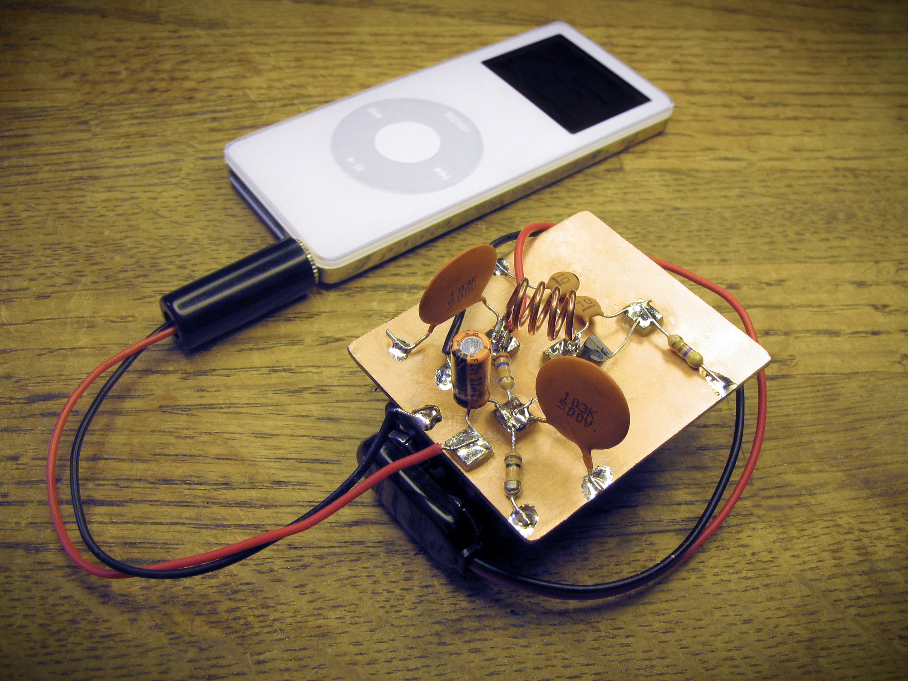
This design was originally popularized by Japanese multimedia artist Tetsuo Kogawa. The circuit itself is a slight variation on Kogawa’s simplest FM transmitter design, and the method of building it is sometimes referred to as “Manhattan style.” It uses a piece of copper-clad circuit board but, rather than etching the circuit traces through the copper layer, a large piece of continuously-plated board is used to make all the circuit’s ground connections, and small sections of plated board are glued to the surface to form nodes or “pads” that are insulated from ground.  Besides being a convenient way to assemble circuits using minimal tools, this building method encourages you to think about circuits in an interesting way — as groups of connections that are either grounded or “floating above” ground.

kogawa_simplest_transmitter

This transmitter uses ten on-board components and will transmit a monaural audio signal about 30 feet. It is possible to extend that range by adding an antenna, and Mr. Kogawa’s website has more information about how to do that.

title_001

NOTE: Depending on where you live, operating an FM transmitter — even a very short-range one like this — may be illegal without a license. Unless you attach an antenna, it’s very unlikely that anyone will notice or complain about any transmissions you may make with this device. On the other hand, it’s very difficult to predict, before construction is complete, just where on the FM band this transmitter will broadcast. Use due caution during testing, and make sure you understand the law in your area before attaching the battery.

Project Steps

Form the coil.

Strip about 4″ of 18AWG solid copper wire and wind 4 turns around the threads of a 1/4-20 bolt.

Turn the coiled wire off the bolt as if you’re unthreading a nut, and clip each lead to about 1cm.

Bend little “feet” on the ends of the leads and adjust them so the coil will stand upright.

Holding a pair of pliers in each hand, grab the coil’s leads and stretch it evenly along its length until the feet are 12mm apart on center. You may need to even out the coil spacing with a screwdriver or other tool.

Cut the board.

Use a straightedge, a utility knife, and the edge of a table to score and snap a 5cm × 4cm rectangle from the copper-clad board. This will be your ground plane.

Score and snap a 5mm × 5cm strip of copper-clad board, then score it crosswise at 5mm increments. Snap along these lines, with pliers, to create several 5mm × 5mm “pads.” You only need 5, but you may want to make a couple extra.

Smooth the corners and edges of the ground plane and the pads with a small file. Be especially careful to remove any sharp copper burrs that might cause cuts on handling.

Mount the coil.

Apply a small drop of cyanoacrylate glue to the underside of one of the pads. It doesn’t take much. Use tweezers or small pliers to carefully position it in the center of the ground plane. Wait a few seconds for the glue to set.

Glue a second pad to the board, above and to the left of the first, along a line running at about 135° with respect to the long centerline of the board, as shown. Position the second pad along this line so that there’s about 12mm between the centers of the first and second pads. Wait a few seconds for the glue to set.

Solder the coil across the 2 pads as shown. This will be easiest if you pre-tin the surface of each pad, and both coil feet, before applying heat to reflow the solder and join the tinned areas.

Add capacitor C3 and resistor R2.

Solder a 0.01μF ceramic disk capacitor (C3) between pad 2 and the ground plane, and trim away any excess leads. It doesn’t especially matter where you connect to the ground plane, for this or any other connection in the project.

Glue pad 3 to the board somewhere below and to the left of pad 2, as shown. You want enough space between pads 2 and 3 to fit the body of a 1/4W resistor.

Solder a 1/4W 27K resistor (R2) between pads 2 and 3, as shown. Trim any excess leads.

Add the electrolytic cap, resistor R1, and capacitor C2.

Glue pad 4 to the ground plane just to the left of pad 3. Space the pads to match the lead spacing on your electrolytic capacitor. Solder the electrolytic cap (C1) between pads 3 and 4, making sure the negative (–) lead is connected to pad 4.

Solder a 10K resistor (R1) between pad 3 and ground.

Solder a 0.01μF ceramic disk capacitor (C2) in parallel to the 10K resistor between pad 3 and ground.

Add the transistor.

Bend the transistor’s 3 leads, as shown.

Glue pad 5 to the board directly to the right of pad 1. Make sure it’s close enough to pad 1 that one of your transistor’s leads can reach between them.

Solder your transistor across pads 1, 3, and 5, as shown. The collector connects to pad 1, the base to pad 3, and the emitter to pad 5. Trim any excess leads.

Add the 10pF caps, resistor R3, and the battery clip.

Solder one 10pF ceramic disk cap (C5) across the transistor’s collector and emitter, (i.e. between pads 1 and 5), and a second 10pF ceramic disk cap (C4) between pad 1 and the ground plane. Trim any excess leads.

NOTE: For more convenient adjustment of the transmitting frequency, replace the 10pF capacitor (C4) between pad 1 and ground with a 20pF variable or “trim” cap. If you use a variable cap, the frequency can be adjusted simply by turning the trimmer shaft with a small screwdriver.

Solder a 470Ω resistor between pad 5 and the ground plane. Trim any excess leads.

Connect a 9V battery clip to the board, as shown, by soldering the red lead to pad 2 and the black lead to the ground plane.

Attach the phone plug.

Unscrew the threaded housing from the tip-shield (TS) mono phone plug and set it aside. Solder a 4″ length of red stranded wire to the center “tip” contact, and a 4″ length of black stranded wire to the outer “shield” contact.

The shield contact has built-in prongs that can be crimped over onto the wires to provide strain relief for the solder connections. Use small pliers to fold these prongs over and crimp the wires beneath them, being careful not to crimp so hard you damage the wire insulation, bend the tip contact onto the shield contact, or otherwise short the 2 connections.

Slip the threaded housing over the wires and tighten it onto the plug threads again. Solder the free end of the red wire to pad 4, and the free end of the black wire to the ground plane.

Tune it up!

Attach your 9V battery to the battery clip and insert the phone plug into an audio source like an MP3 player or smartphone. Start a song or other easily-recognizable audio track playing, then turn on your radio and scan through the FM band to locate the transmission.

TIPS:

  • Start with your receiver right next to the transmitter.
  • A digital tuner with precision down to 0.01MHz may be helpful.
  • Be patient and careful. Scanning is a bit tedious, but if you get impatient you may miss the signal altogether and mistakenly believe the transmitter isn’t working.

  • If you scan the entire band and can’t locate your signal, try changing the orientation of your receiver’s antenna with respect to the board and scanning again.
  • It’s best to run your audio source on battery power when you are first isolating the transmitting frequency. If you have to run it from mains power, make sure electrically noisy devices like fluorescent lights, TVs, and computer monitors are not active on the same circuit at the time.

You can tune the transmitting frequency by changing the spacing between turns in the coil. Closing the spacing will lower the transmitting frequency, while opening it up will raise the transmitting frequency. You can also use a variable capacitor for tuning (see Step 7).

Mount the battery.

NOTE: This transmitter design needs very clean, smooth power, which is one of the reasons we choose to run it from a battery. Power from a “wall wart” or other AC adapter is smooth enough for most DC applications, but not for this radio transmitter. Using an AC adapter to power this transmitter is likely to cause the signal to be too noisy to use.

Use scissors to cut a strip of hook-and-loop fastener (velcro) tape to fit the length of your 9V battery.

Separate the hook and loop sides of the tape, remove the backing from each, and apply the hook (scratchy) side to the bottom of the transmitter board. Apply the loop (fuzzy) side to one of the battery’s 2 largest faces.

Attach the transmitter to the battery using the velcro during use. When depleted, the battery can be removed and separated from the transmitter for recharging.