At work, I often use a Post-it note stating my whereabouts on my office door for those who stop by looking for me when I am out. Some notes are one-time use like “On vacation. Back on 11/20.”, and some can be reused like “Up in the 3113 lab.” Sometimes, though, I am late to return from a previous meeting or am home sick. In these cases, I would like to be able to update my status.
The solution I came up with was to use an Arduino Uno and a GSM shield that allows me to send a text message to the Arduino/GSM. Once in the Arduino, the text message is extracted, manipulated a bit, and then displayed scrolling across a 16×2 LCD affixed to my office door. To mount the display on the door, a bracket was made with a 3D printer, and a cable connects the Arduino to the LCD.
This project is my first with Arduino, not counting turning an LED on with a push button. It is a combination of getting the GSM side of things to work and programming the message for the LCD. There are lots of opportunities to make tweaks to fit your particular needs, especially how to mount the display.
The code and related files can be found at the GitHub repository for this project.
Project Steps
Receive a Text Message
Attach the GSM shield onto the Arduino Uno via the connectors. Install the SIM card. You will need to activate the SIM card if you are using a new one.
Connect the Arduino to your laptop via the USB. The USB port supplies enough power for this step.
Follow the Arduino GSM Receive example. It is well documented, and will get you acquainted with the steps of initializing the GSM modem, detecting a message, and extracting a message.
Once you have the GSM example running, make a couple modifications. (1) Add some security to reduce the chance that a friend pranks you with a message that you are, well, use your imagination. I added a check that allows only texts from my cell phone to be displayed. Others are flushed. (2) Add code that saves a verified text message in a variable, txtMsg, and determines its length as the variable is needed for the display.
// Any messages not coming from my cell number should be discarded.
if( strncmp( senderNumber, myCellNumber, 12 ) != 0 ) // strncmp returns 0 if match
{
Serial.println("Discarded SMS"); // Diagnostic
sms.flush();
}
else {
// Read message bytes and save them
i = 0;
while( c = sms.read() ) {
Serial.print(c); // Diagnostic
// save the message character by character and keep track how many chars in message
txtMsg[i] = c;
i++;
validMessage = 1; // there is a valid message
}
numChars = i; // the number of characters in txtMsg
}
A standalone sketch you can run that has the modifications is ReceiveSMS_modP.ino. You’ll need to set the variable myCellNumber with your cell number. It starts with the + sign.
If you occasionally have GSM connection issues like I did … a sent message did not appear to be received … then check out the GSM Scanner class GSM Scanner class to help figure out what is going on.
LCD and Manipulating Characters
If you already know how the basics of wiring up a 16×2 LCD and displaying a message, then you can skip this substep. If this is new for you (as it was for me), then go and do the Hello World example example at the Arduino site.
Note: The example from Arduino assumes just the Uno is being used (no GSM shield attached). If the GSM shield attached, then you’ll need to change the digital pins used to drive the display as the GSM shield uses two pins the Arduino LCD example uses. It is an easy fix in the code and wiring:
/* initialize the library with the numbers of interface pins:
LCD RS pin to digital pin 12
LCD Enable pin to digital pin 11
LCD data pin D4 to digital pin 5
LCD data pin D5 to digital pin 4
LCD data pin D6 to digital pin 6 // changed for GSM shield
LCD data pin D7 to digital pin 8 // changed for GSM shield
*/
The next step builds off of the Hello world example. I put a title for the display in the first row as part of Setup, and also added to Setup code that allows a char array to be entered from the keyboard. This allowed me to not have to deal with the GSM modem every time I had to fix a bug. Borrowed approach from SendSMS.ino in the Arduino GSM examples.
The LCD library scrolling function didn’t do what I wanted, so I wrote my own. After a few iterations, scrolling worked well enough. Here is a fragment of the main scrolling control:
if ( numChars <= 16 ) {
// message does not need scrolling
for (i = 0; i < numChars; i++) {
lcd.setCursor(i, 1); // format is col,row
lcd.print(txtMsg[i]);
}
}
else {
// logic for how far to scroll. scroll length of message minus the
// part that displays at first. q controls number of scroll events.
for ( int q = 0; q <= numChars - 16; q++) {
// print out just one char at a time, and repeat for each column
for (i = 0; i < 16; i++) {
// send the LCD a set of 16 chars based on position in txtMsg
// determined by indexing based on q start position.
lcd.setCursor(i, 1); // i prints to a column
lcd.print(txtMsg[i+q]);
if (q == 0 && i == 15) {
// detects the first 16 chars that are displayed before
// scrolling begins
delay(1800); // pause time to read the starting 16 chars
}
}
delay(500); // time for the scroll delay
}
}
There is also a code section that blanks out the message, and then the message repeats.
StringManipulateLCD_modP.ino is a self-contained sketch is available to exercise the LCD part of the project.
Put It Together
Now that you separately have the GSM part working and the LCD part doing its thing, merge the two sketches. Or you can grab GSMTextMessage2LCD_modP.ino from repository that has it already done. For the hardware, if you already have the LCD connected from the GSM shield, then you are all set, otherwise put on the GSM shield and wire up using the pins shown in Step 1.
Setup() is pretty much the same as in the GSM test sketch. I did add additional diagnostics that show the cell carrier that connected and the signal strength. A few of the GSM startup messages that show up on the serial console (laptop display) were duplicated to show up on the LCD. This is helpful once the project is running on its own without the laptop connection.
// include the GSM library
#include
// include the LCD library
#include
// PIN Number for the SIM
#define PINNUMBER "" // "" means no PIN is used
/* initialize the library with the numbers of interface pins:
LCD RS pin to digital pin 12
LCD Enable pin to digital pin 11
LCD data pin D4 to digital pin 5
LCD data pin D5 to digital pin 4
LCD data pin D6 to digital pin 6 // changed for gsm shield
LCD data pin D7 to digital pin 8 // changed for gsm shield
*/
LiquidCrystal lcd(12, 11, 5, 4, 6, 8); // free pins when GSM shield used
// initialize the library instances
GSM gsmAccess;
GSMScanner scannerNetworks;
GSM_SMS sms;
char senderNumber[20]; // char array to hold the number a SMS is retreived from
char txtMsg[200]; // the text message char array
int numChars = 0; // number of characters in txtMsg
int validMessage = 0; // set to 1 when there is a message to display
char myCellNumber[] = "+XXXXXXXXXXX"; // used for message screening
void setup()
{
// initialize serial communications and wait for port to open:
Serial.begin(9600);
// set up the LCD's number of columns and rows
lcd.begin(16, 2);
// connection state
boolean notConnected = true;
// provide information to LCD as GSM gets started
lcd.print("GSM starting up ...");
// Start GSM connection
while(notConnected)
{
if(gsmAccess.begin(PINNUMBER)==GSM_READY)
notConnected = false;
else
{
lcd.setCursor(0,1); // format is col,row
lcd.print("Initializing...");
// delay(1000);
}
}
// currently connected carrier
Serial.print("Current carrier: ");
Serial.println(scannerNetworks.getCurrentCarrier());
lcd.clear();
lcd.setCursor(0,0);
lcd.print("Current carrier:");
lcd.setCursor(0,1);
lcd.print(scannerNetworks.getCurrentCarrier());
delay(1000);
lcd.clear();
// returns strength and ber
// signal strength in 0-31 scale. 31 means power > 51dBm
// BER is the Bit Error Rate. 0-7 scale. 99=not detectable
Serial.print("Signal Strength: ");
Serial.print(scannerNetworks.getSignalStrength());
lcd.setCursor(0,0);
lcd.print("Signal Strength:");
delay(1000);
lcd.setCursor(0,1);
lcd.print(scannerNetworks.getSignalStrength());
delay(2000);
lcd.clear();
// print one time message to the LCD
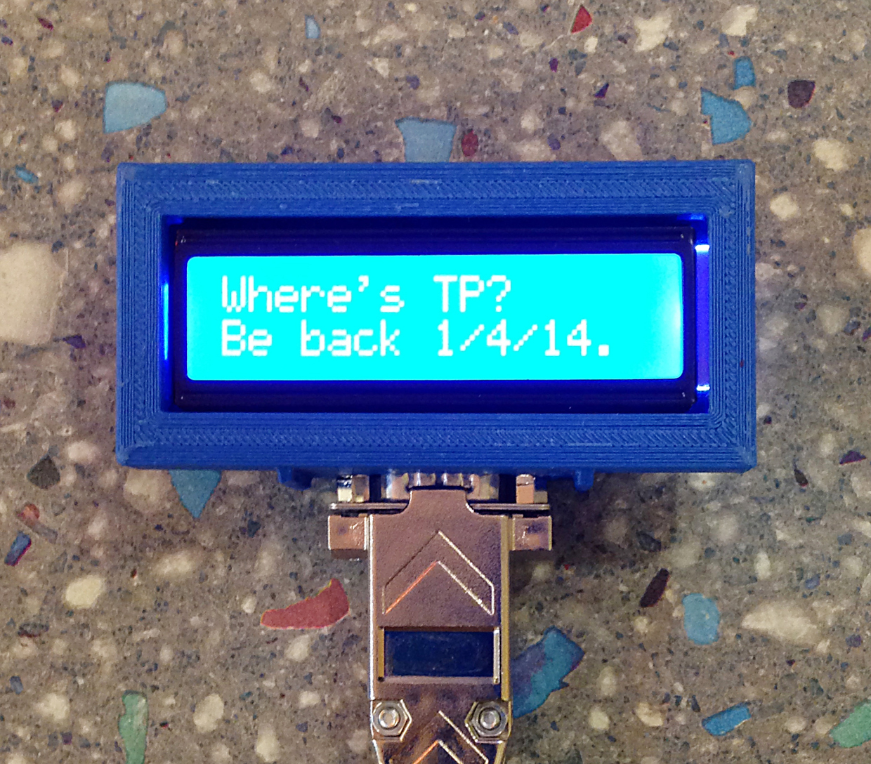
lcd.setCursor(0,0); // format is col,row
lcd.print("Where's TP?"); // first row
lcd.setCursor(0,1); // format is col,row
lcd.print("Waiting for SMS");
Serial.println("Waiting for SMS"); // Diagnostic
}
The Loop() now has two main sections: (1) check for and save new text messages and (2) print the valid text message to the LCD, scrolling as needed. The sketch checks for a new message each time through the code.
void loop()
{
char c;
int i; // char array index of txtMsg
int validMessage; // set to 1 when there is a message to display
// If there are any SMSs available()
if (sms.available())
{
// show on display that a text message has been received
lcd.setCursor(0,1); // format is col,row
lcd.print("SMS received");
delay(2000);
// Get remote number
sms.remoteNumber(senderNumber, 20);
Serial.println("Message received from:"); // Diagnostic
Serial.println(senderNumber); // Diagnostic
// Any messages not coming from my cell number should be discarded.
if( strncmp( senderNumber, myCellNumber, 12 ) != 0 ) // strncmp returns 0 if match of 12 chars
{
Serial.println("Discarded SMS"); // Diagnostic
sms.flush();
}
else {
// Read message bytes and save them
i = 0;
while( c = sms.read() ) {
Serial.print(c); // Diagnostic
// save the message character by character and keep track how many chars in message
txtMsg[i] = c;
i++;
validMessage = 1; // there is a valid message
}
numChars = i; // the number of characters in txtMsg
}
// Delete message from modem memory
sms.flush();
Serial.println("MESSAGE DELETED");
} // end of if sms.available section
if ( validMessage ) {
// now print the message to the LCD.
// if there is only one row, print it all at once, else
// do scrolling.
if ( numChars <= 16 ) {
for (i = 0; i < numChars; i++) {
lcd.setCursor(i, 1); // format is col,row
lcd.print(txtMsg[i]);
}
}
else {
// logic for how far to scroll
for ( int q = 0; q <= numChars - 16; q++) {
// print out just one char at a time, and repeat for each column
for (i = 0; i < 16; i++) {
lcd.setCursor(i, 1); // i prints to a column
lcd.print(txtMsg[i+q]);
if (q == 0 && i == 15) {
delay(1800); // time to read the starting 16 chars
}
}
delay(650); // time for the scroll delay
}
}
delay(1000); // time to hold the last line fragment
// blank out the display after the scrolling has completed to prepare repeat
for (i = 0; i < 16; i++) {
lcd.setCursor(i, 1); // format is col,row
lcd.print(' '); // blank out the second row
}
delay(2000); // time the display is blank
} // end of if validMessage section
}
Door Version
This next step takes the LCD off of the prototyping board and onto a door near my desk. It involves connectors and a cable as well as a bracket to hold the display. If you are content with the protoboard version, then you can skip this work.
Finding a bracket to hold a 16×2 LCD in a catalog wasn’t panning out, so when someone suggested printing one, I said, “I’ll think about it.” It wasn’t the plan to learn a 3D drawing program and printing. After a bit of poking around on Thingiverse, I found a bracket that was close enough. I rendered and added section to which a DB9 connector could be attached. Learning the CAD program Tinkercad was pretty easy as graphics programs go. The part was ready to print. Printing was done on a Makerbot2 at the TechShop in my area. There was a little bit of trimming to do, but the fit is nice and snug. The stl-file is at the github repository for the project.
Building up the cable and connectors was tedious. I used Sub-D 9 pin connectors and a 10 conductor cable to go from the display back to the input output board. A small section of vector board was used to facilitate going from the Arduino/GSM shield to the cable connector. The wiring is schematically the same as the LCD on the prototyping board, except for the connectors. I’m sure there are better ways to wire this, but this was good enough for me.
The display bracket was affixed to the door glass with transparent mounting sticky things. It has held for a couple weeks.
The only change made from the prototype was to go to a blue backlit LCD display. The first display (green with dark characters) was hard to see once mounted on the door. The blue display takes care of that problem. I didn’t solder the pin rail to the LCD for the door version.
You may come up with a different mounting and wiring scheme depending on where you want to put your remote display.