The Maiden Flight

There are essentially two configurations for a quadcopter: the “+” frame and the “X” frame. Here we’ve chosen to build an “X” frame so your onboard camera can have a clear forward view.

prop-rotations

We’ll take you all the way from building the airframe to adding autonomous flight capability with ArduPilot. Once you’ve got it working, you could program this drone, for instance, to automatically visit a series of landmarks or other waypoints and take pictures of them.

Wiring Diagram

Diagram by Sam Freeman for MAKE Labs Graphics by Rob Nance
Diagram by Sam Freeman for MAKE Labs
Graphics by Rob Nance

Project Steps

Fabricate the body

The copter’s central hub consists of 2 polycarbonate plates. Download the cutting and drilling templates here, print them full-size, and affix them temporarily to your polycarbonate sheet. Use a plastic cutter to score and snap each plate to shape, then drill out the holes with a ⅛” bit.

Cut and drill the booms

Saw 4 square dowel booms to 10″–11″ each. Shorter booms will make your quad more agile, and longer booms will make it more stable. Drill two 3mm holes, one 6mm and one

26mm (on-centers) from the end of each boom.

Assemble the frame

Secure the booms between the hub plates using four M3×25mm screws through the inner holes and four M3×20mm screws through the outer holes. Once the booms are in place and you’re happy with the fit, apply thread-locking compound to the outer screws only, add nuts, and tighten them down. Thread the inner nuts on just loosely, for now.

Wire the power hub

Six components will connect to the power hub — the 4 electronic speed controllers (ESCs) , the power module, and the gimbal controller board. First, cut off the male XT60 connector from the APM power module cable. Then strip about ¼” of the insulation from each wire, red and black, on all 6 components, and tin the stripped ends. Saw a ⅜” ring from each end of the copper reducer, and file off any rough edges. Solder each of the 6 red positive leads to the smaller ring, and the corresponding 6 black negative leads to the larger ring. Wrap the smaller ring in ⅜” foam weatherstripping tape and slip the outer ring over it. Finally, paint the entire hub with liquid electrical tape for insulation.

Wiring the motors and electronic speed controllers together is tedious. Store-bought distribution boards are convenient, but cost space and weight. I prefer this homemade distribution hub made from 2 rings of nested copper pipe to keep things lean and tidy.

Drill motor shaft clearances

Here we’ll show you how to make your own landing struts from ordinary conduit clamps. You can also use inexpensive prefab combination landing gear / motor mounts that simplify the process quite a bit, and look better to boot. Please check out our product line at flitetest.com if you’re interested in the prefab option.

If you go the homemade route, you’ll be mounting the motors directly to the booms. Mark and drill a shallow blind recess in each, so the shaft can spin freely. A 516″ bit works well for this.

Mount the motors

Cut down the bracket that came bundled with each motor and use two M3×20mm screws to clamp a motor to the end of each boom. Verify that each motor shaft spins freely when the screws are fully tightened. If not, double-check that its boom is properly recessed underneath. Smooth any rough edges on the bracket with a file.

Add the landing gear

Slip the power hub between the top and bottom body plates and route the ESC power leads out along the 4 booms. If you bought motors and ESCs from the same manufacturer, there’s a good chance they came with preinstalled “bullet” connectors. In this case, simply plug the motor leads into the ESC leads and coil any slack under the boom. Or you can solder the motor wires directly to the ESC boards for a cleaner build. Secure the motor leads, the ESC power leads, and any leftover slack tightly against the booms with zip ties.

Use wire cutters to snip off one side of each of 4 conduit clamps, leaving a J-shaped foot behind. Smooth the cut end with a file, then file or grind 2 small notches beside the remaining mounting hole as shown. Attach a foot to the end of each boom, just inside the motor mount, using a zip tie run through these notches.

Install the shock mounts

Remove the hose clamps from the flexible PVC coupler and save them for another project. Cut two 3/4″ rings from the coupler’s rubber body with a sharp hobby knife. Align each ring across 2 of the frame’s protruding inner screws and press down hard with your thumbs to mark 2 drilling spots. Drill ⅛”-diameter holes on the dents, through one side of the ring only. Install the rings over the frame screws with M3 flat washers and nuts. Secure with thread-locking compound when you’re happy with the fit.

The gimbal and battery shelf are attached via 2 shock mounts cut from thick flexible rubber tubing, which helps isolate the camera from propeller vibrations and adds a bit of space, above, to mount the gimbal controller board.

Build the camera/ battery mount

The gimbal and battery shelf are assembled from three simple L-shaped brackets. We refer to these as the shelf, roll, and pitch brackets.

Saw a 36″ length of ⅛”×¾” aluminum bar stock into two 18″ sections, then saw one of those into two 9″ sections, giving 3 pieces total. Make a right-angle bend in each section as indicated on the templates, working over a piece of wood or other scrap with a beveled edge to increase the bend radius to about ⅜”. (Too sharp a bend can overstress and weaken the aluminum.) After you’ve made the bends, cut each bracket to final size per the templates.

Accurately locate, mark, and drill a centered row of three ⅛”-diameter holes on the short leg of the shelf and pitch brackets, and on both legs of the roll bracket. In each case, the outermost hole should be 3mm from the bracket end on-center, and the holes themselves 9.5mm apart on-centers. Finally, step-drill the center hole in each row up to ⅜” to provide clearance for the motor shaft.

Use two M3×6mm screws to attach the bottom of a gimbal motor to the shelf bracket, and then 2 more to attach the top of the motor to the longer arm of the roll bracket.

Attach the bottom of the second

motor to the free arm of the roll bracket, and its top to the pitch bracket, in just the same way.

Mount the camera and battery

I designed this quad to balance properly with a 3S 2,200mAh LiPo battery and a GoPro Hero3 White. If you use other equipment be sure you keep the CG (center of gravity) in the middle of your airframe. Here’s how to get it balanced.

TIP:

Though the GoPro is a tough camera, you may want to build a “dummy” version having the same weight, and approximately the same size, to mount during your maiden and subsequent shakedown flights.

For the gimbal motors to operate smoothly, the camera must be balanced along both axes. Weaken the adhesive on a piece of double-sided tape by sticking it to your shirt and peeling it off. Remove the backing and apply the exposed side to the pitch bracket, then use the weakened side to hold your GoPro in place while you adjust it to find the balance point. Once you’ve got it, use an elastic band or a velcro strap, in addition to the tape, to hold the camera securely in place.

With the frame upside-down, balance the camera, brackets, and battery across the 2 shock mounts on the underside of the frame. Adjust the position of the whole assembly forward and backward along the frame until the entire quad balances evenly between your fingertips, centered on either side of the body.

Once you’ve got the CG right, fix the shelf bracket to the shock mounts with 2 sets of crossed zip ties. Apply hook-and-loop tape on top of the shelf bracket and on the underside of the battery, and fix the battery in place. Add a hook-and-loop strap around both bracket and battery as an added precaution.

Install the avionics

Arrange your flight controller, receiver and other modules before attaching them to the airframe. Once you’re happy with the layout, use double-sided tape to secure everything to the frame. Download the wiring diagram for a detailed list of all connections.

Attach the flight controller. In this build we use 3D

Robotics’ ArduPilot Mega (APM) 2.6, which contains an accelerometer and must be oriented correctly with respect to the frame. Align the arrow on the APM case toward the front of the quad and fix it in place with double-sided tape.

Add the GPS/compass module, which fits neatly on the rear extension of the bottom frame plate, and also must be aligned with the arrow forward. Tape the module in place and connect the cable to the APM’s “GPS” port.

Starting from the starboard-front position and proceeding clockwise (viewed from above), connect the ESC signal cables to APM outputs 1, 4, 2, and 3.

Mount the receiver alongside the APM with double-sided tape, and connect channels 1–5 to the corresponding inputs on the APM.

Install the gimbal controller

The gimbal controller consists of 2 boards: the larger controller board and the smaller IMU sensor unit. The controller board goes above the shelf bracket, in the space provided by the shock mounts.

Cover the top surface of the bracket with foam weatherstripping to keep the solder points from shorting against the bare aluminum, then fix the controller board to it with zip ties. The IMU detects the orientation of the camera and needs to be mounted in the same plane; fix it to the underside of the pitch bracket with double-sided tape, and run the connector cable back to the control board. Connect the 3 wires from each gimbal motor to the ports on the controller. Secure all wires with zip ties, leaving plenty of slack for the gimbal to rotate freely.

Configure the software

The flight controller, ESCs, and gimbal controller all need to be calibrated and configured before flight. Refer to the bundled or online instructions that came with your equipment. Specific tutorials are linked from the bottom of this page.

Add the props

Before you install the propellers, put bits of masking tape on the motor shafts to make it easy to see which way they are spinning. From above, motors 3 and 4 should spin clockwise, and motors 1 and 2 counterclockwise. If a motor is reversed, simply swap any 2 of the 3 leads connecting it to the ESC.

WARNING:If you need to reverse a motor, be sure to swap the motor control leads only, not the ESC power hub leads. Don’t ever reverse the power connections on an ESC!

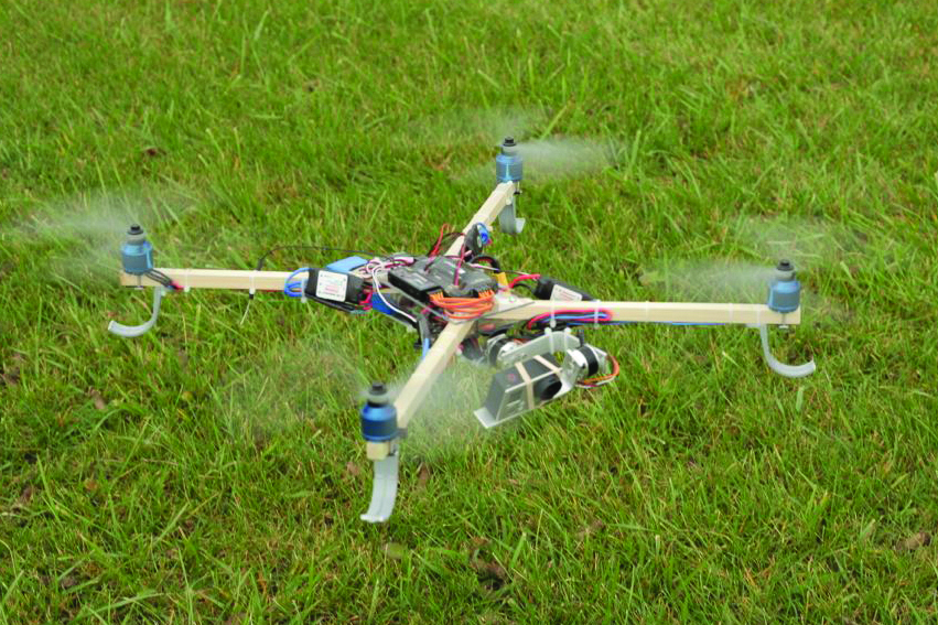
The most important factor for steady flight is balanced props! There are lots of tricks for doing this, but the simplest involves sanding the heavier side of each blade until the prop balances level on a horizontal shaft. (Sand only the flat, not the leading or trailing edges).

Once the props are balanced, install them on the shafts and tighten the nuts. You’ll use 2 conventional airplane “tractor” props and 2 reverse-pitched “pusher” props. Motors 1 and 2 take tractor props, and motors 3 and 4 take pusher props. (If you’re not using the APM flight controller, your prop configuration may be different.) Once you’ve got it right, mark the number and direction of rota-

tion for each motor on its boom for easy reference.

Make sure the props are balanced, the parts are securely fastened, and none of the props, gyros, or controls are reversed. Verify that all your radio trim settings are at zero (if you have to trim, do it through the APM, not the radio). Wait for wind-free conditions to actually make the first flight.

Conclusion

Don’t expect your quad to fly perfectly the first time. You’ll likely need to make some tweaks and adjustments before it flies well. If you’ve never flown a quad before, remember to work the controls gently, as most beginners tend to over-steer. Your first goal should be to hover about 24" off the ground for 1-2 seconds and then immediately land. Once you can do that consistently, try to take off, rise above the “ground effect” zone (3'-4’), and then land gently. Work your way up gradually to longer and higher flights.

It is likely that you will crash at some point, especially if this is your first multirotor. Keep a positive attitude, pay attention, and try to learn something every time. Crashing, learning, repairing, and improving your skills and your machine is part of the fun and challenge of the hobby.

Avionics Resources

Test Builders: Nick Parks, Brian Melani, and Sam Freeman, MAKE Labs