TouchUp is a project initially developed to help a middle-aged woman who lives with multiple sclerosis (MS) in a caregiving facility. Due to the effects of MS, she has limited hand and arm strength to push the buttons on the handheld controller used to adjust her bed, a Hillrom-8400. Our goal was to develop an iPad application that she could use as an alternative to control her bed more easily.

To complete this project, we divided it into three parts: a graphical user interface, an Arduino-to-bed connection, and a network which the Arduino and iPad application communicate over. The approach is as follows:

  • Build a GUI which our client can use to send desired actions to her bed
  • Connect Arduino to the Hillrom-8400 bed using a serial port
  • Establish a network which iPad and Arduino can communicate over
  • Send desired action from iPad to Arduino using an HTTP Get request
  • Arduino sends signal to bed’s actuator based on desired action

What will the next generation of Make: look like? We’re inviting you to shape the future by investing in Make:. By becoming an investor, you help decide what’s next. The future of Make: is in your hands. Learn More.

Project Steps

Download the Arduino IDE

Go to http://arduino.cc/en/Main/Software and download appropriate IDE based on your operating system.

Test that the Arduino works by loading a basic template onto the Arduino Uno.

Basic “blink” template can be found under File → Examples → 01.Basics → Blink

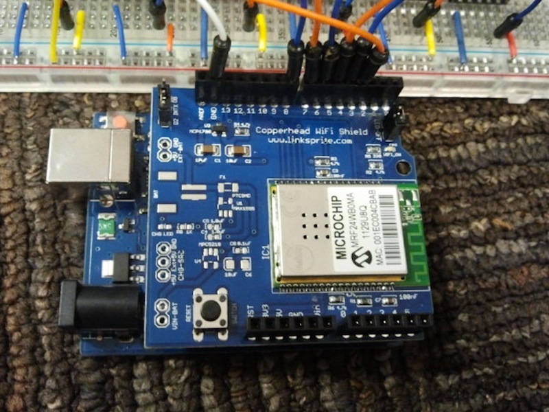
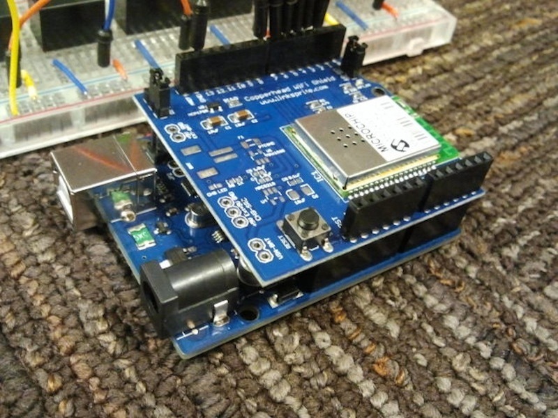
Set up Arduino WiFi Connection

Download the zip file containing the WiShield library and the Arduino code. Keep a copy of the WiShield library under the library folder where the Arduino IDE libraries are kept; the Arduino code folder can be copied to the directory containing any projects.

One option for using the Arduino code is to open the code file and copy the contents into a new Arduino project.

In case the zip file does not work, the library for the LinkSprite CuHead WiFi Shield can be downloaded from here.

Follow the steps in this link to make the library compatible with the new Arduino IDE.

Plug in router and take note of the router’s IP, network SSID, security type, password, and subnet mask.

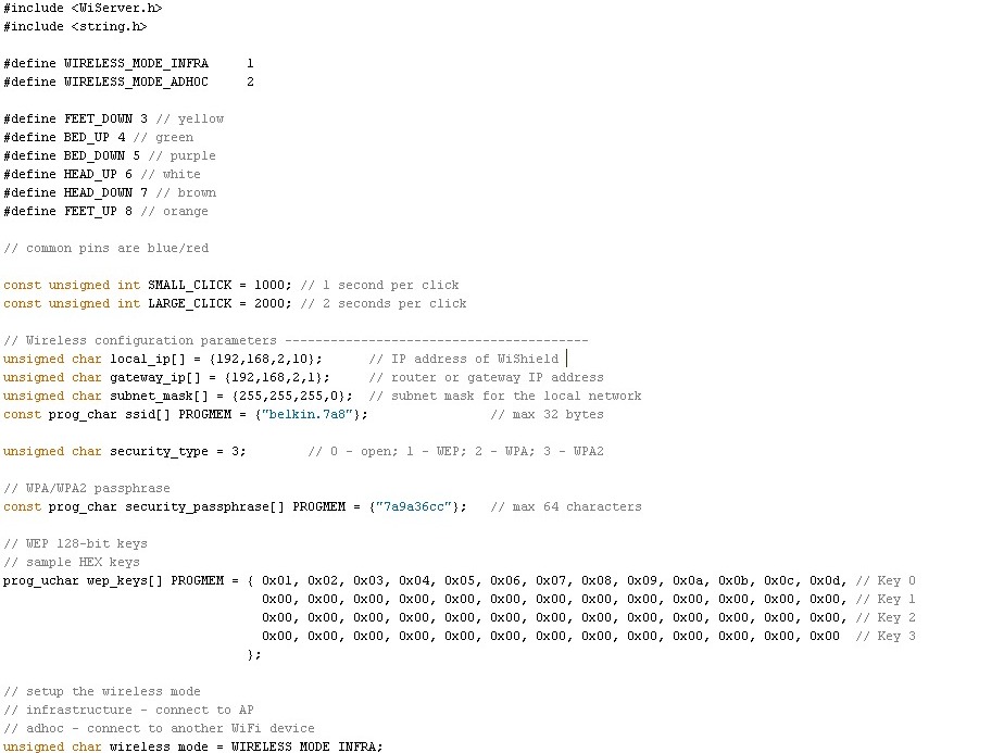
In the Arduino code update the appropriate fields with the values from above (gateway_ip, subnet_mask, ssid, security_type).

Develop iPad Application

Download Xcode to begin developing. If you downloaded the TouchUp zip file, the folder should include code for a graphical user interface already.

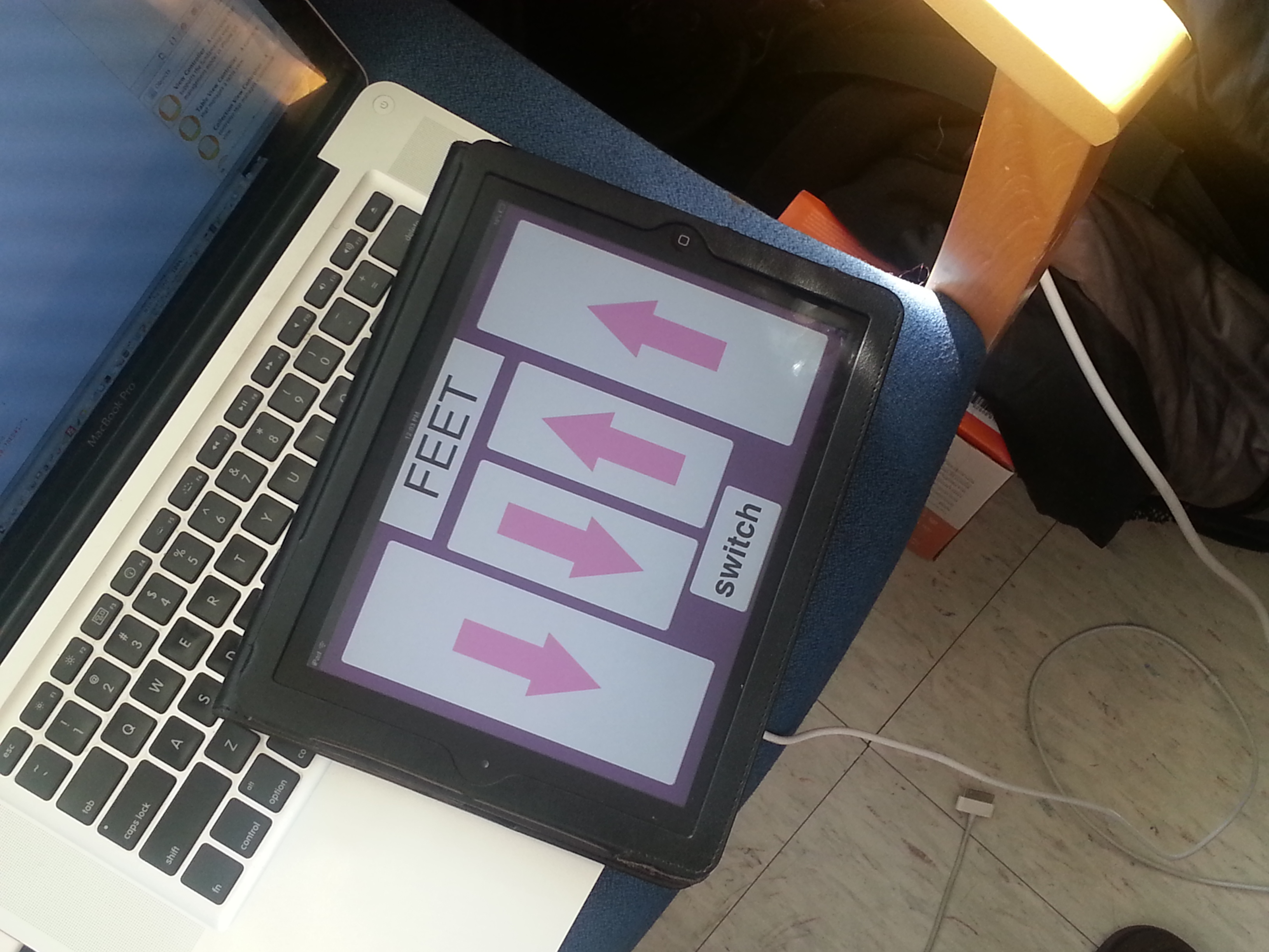
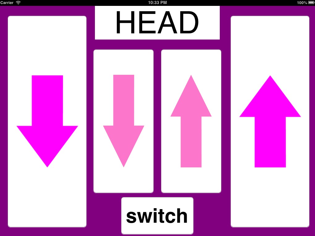
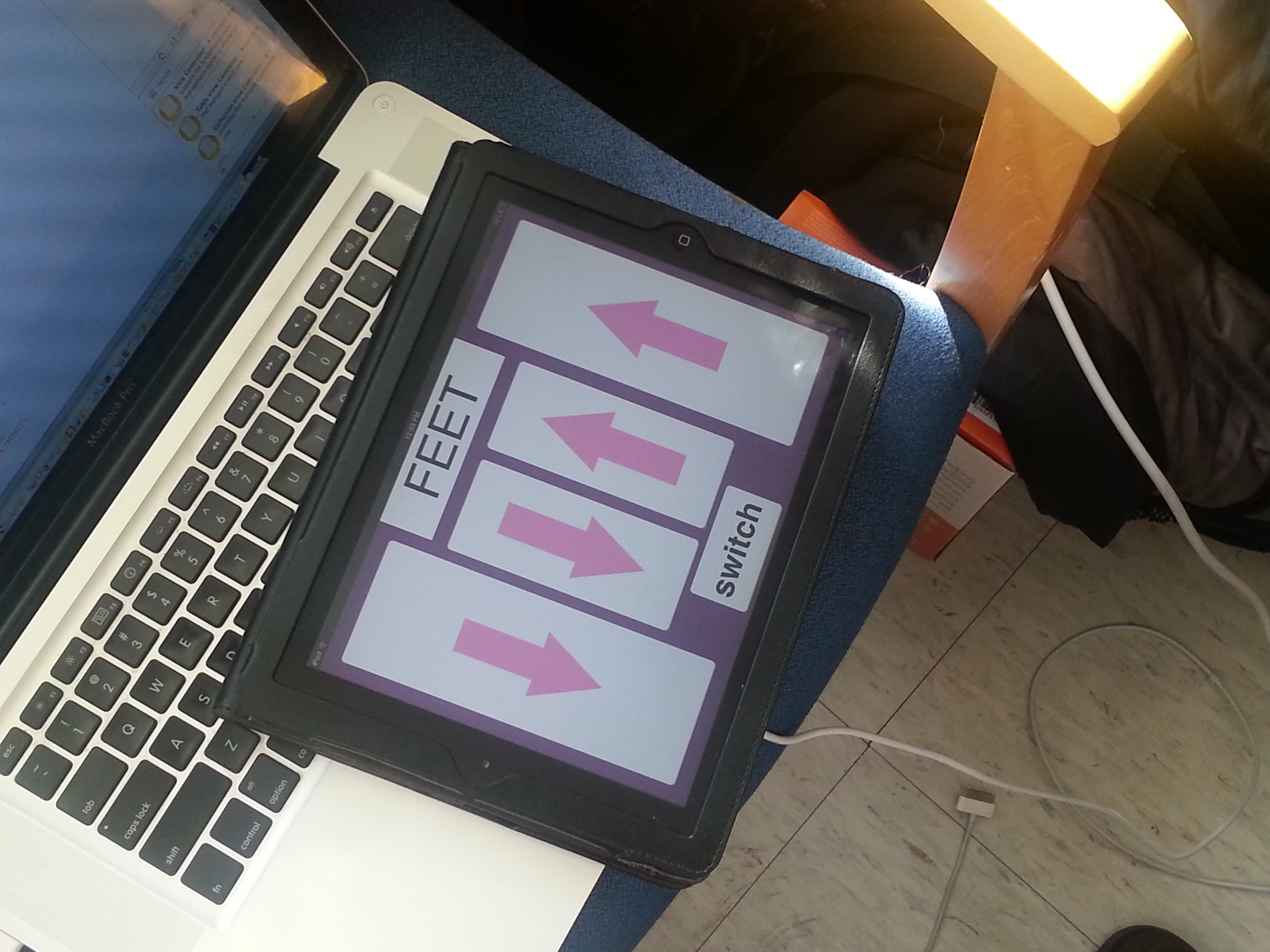
Design a user interface with a total of five buttons and one label. Two of the buttons will be used for moving the bed up, two for moving the bed down, and one to switch modes (Bed, Feet, Head). Refer to iPad application tutorials if you are not familiar with this.

Make sure to change the URL so that it matches the URL of your Arduino.

Test that the GUI can toggle a basic LED set up with the corresponding output pins in the Arduino (use only resistors, wires, and LEDs to do this; do not put the relays in yet).

Set up Relays on Breadboard

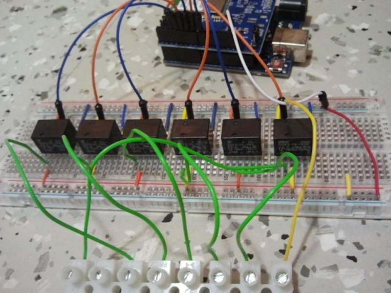
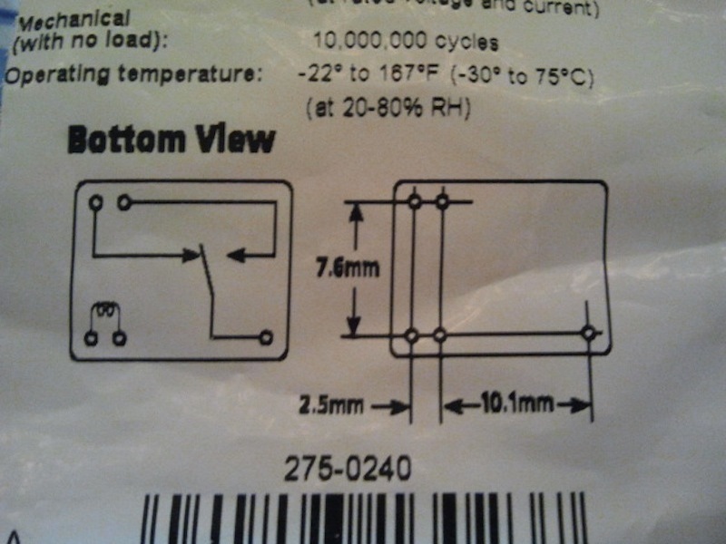
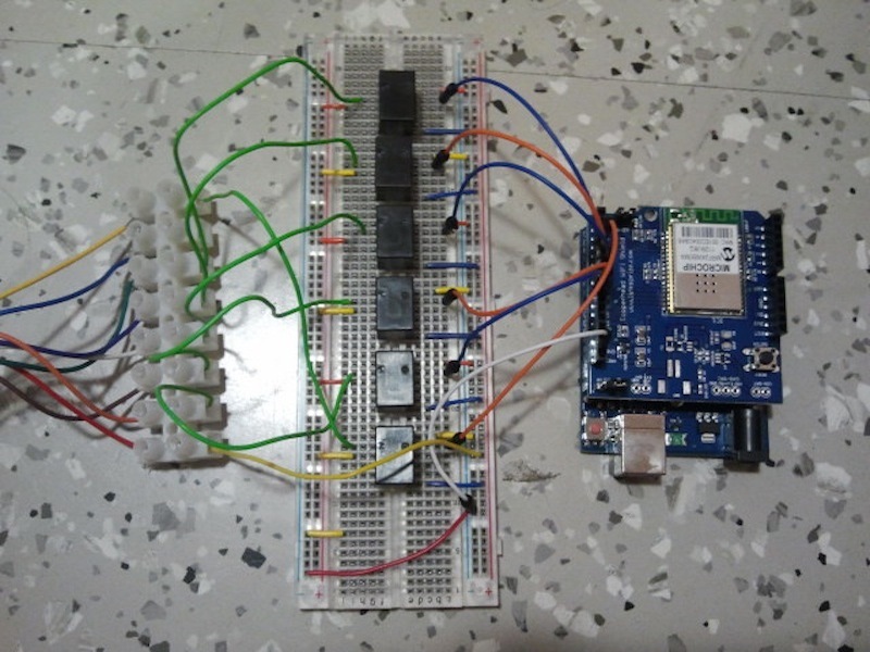
Set up the relays on the breadboard as shown by the diagrams. Spread out the 6 relays across the breadboard.

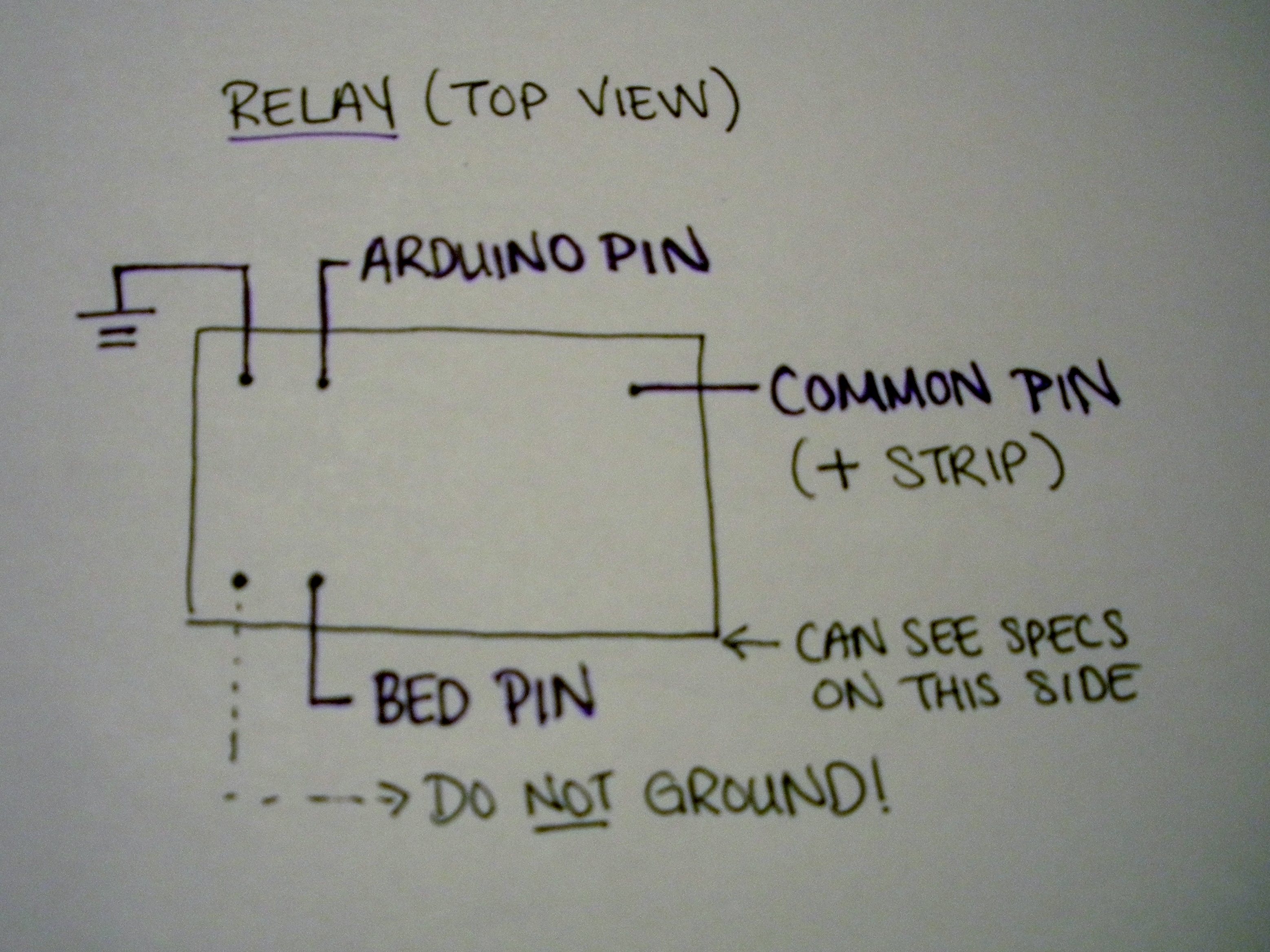
Connect the (-) strip to the ground pin on the Arduino and each relay common pin to the (+) strip.

The bed pins will be connected in the next few steps after the Molex port has been put together.

Make sure the relays are oriented correctly, and do NOT ground the left pin. We used SPDT relays, which would short the rest of the circuit when a switch is “open.” If you find that nothing works after you have put everything together, check that this pin is not connected to anything that shorts the circuit!

Set up Molex Connector

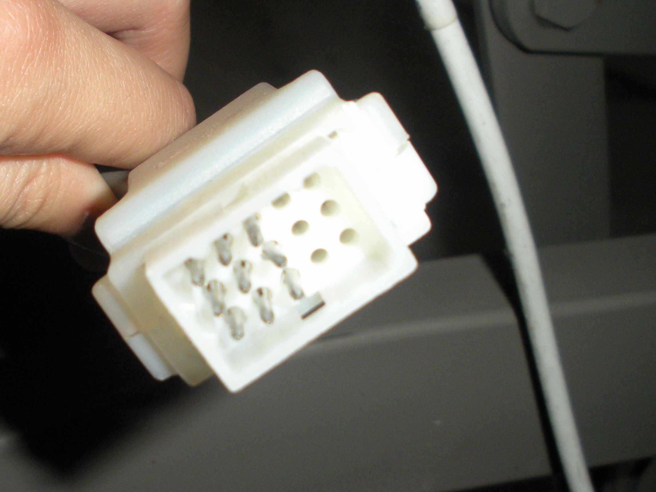
Molex Connector has room for 15 pins, but we will only use 7 male pins from the kit.

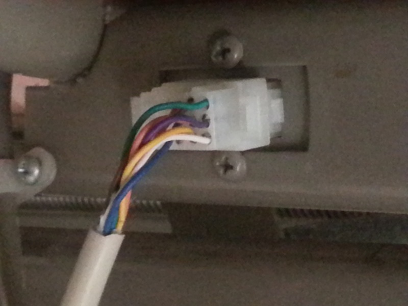
Attach individual wires from the connector cable to terminals using the crimping tool.

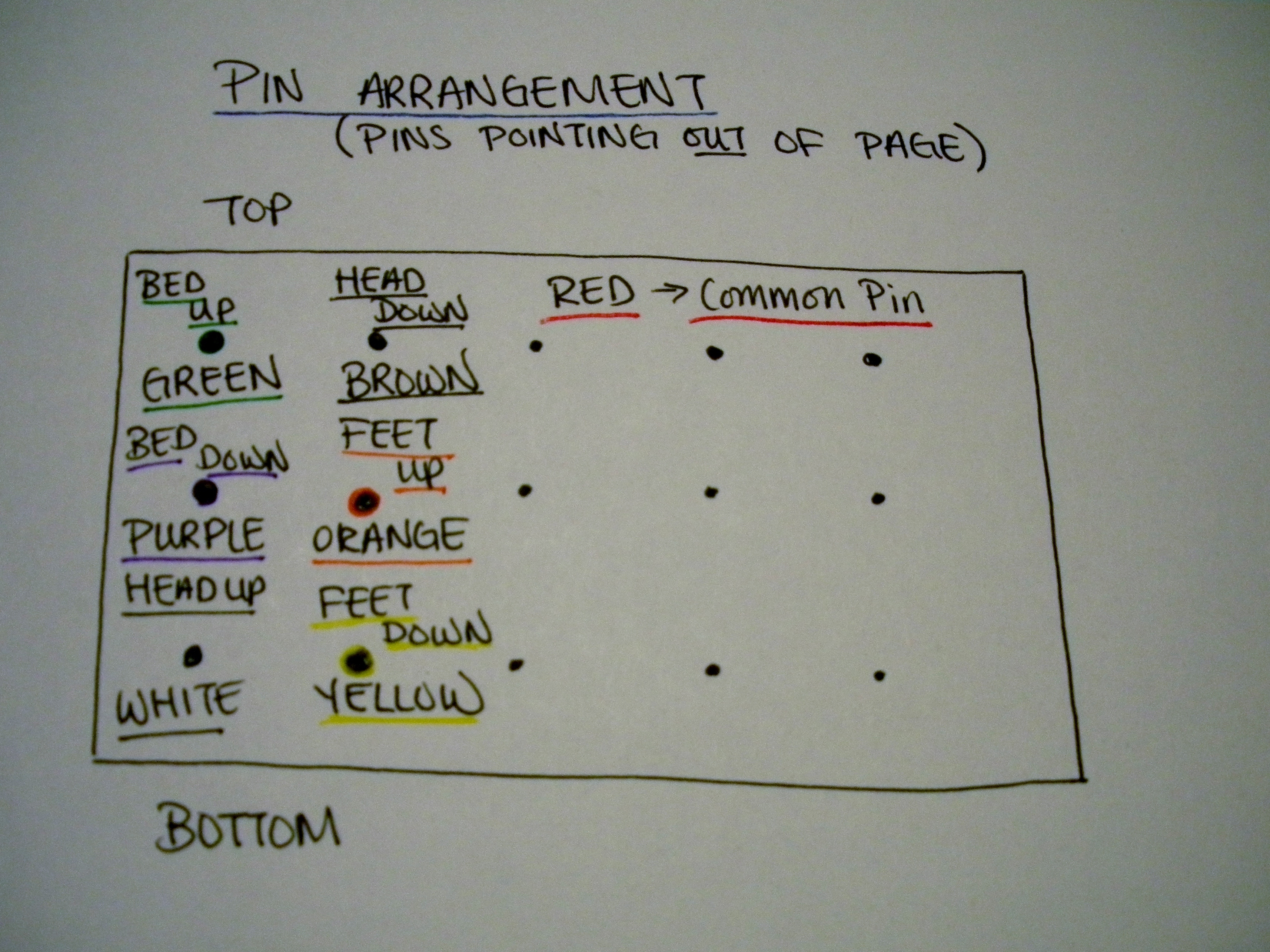
Keep track of which wires connect to which pins — they need to correspond to the correct Arduino output pins.

I kept track by looking at the colors of each wire, which I have labeled in the diagram. Make sure that you are looking at the diagram as if the pins were sticking out towards you.

Any of the three pins down the middle column will work as a common pin. We arbitrarily chose the top pin and attached it to the red wire.

Connect Cable to Breadboard

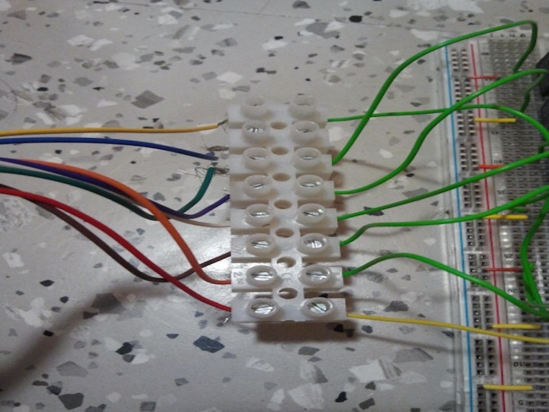
Attach the free ends of the wires from the connector cable to the terminal block.

The wires we used were too difficult to put into the breadboard directly, so we attached stiff wires to the other side of the terminal block. This is only one of many ways to connect the wires securely to the Arduino board.

Make sure that the Common Pin connector is connected to the + strip, and that the Bed Control pins are connected to the corresponding terminals of the relay.

Put Everything Together

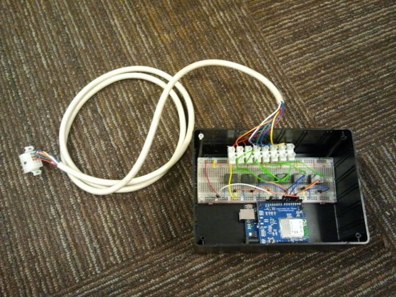
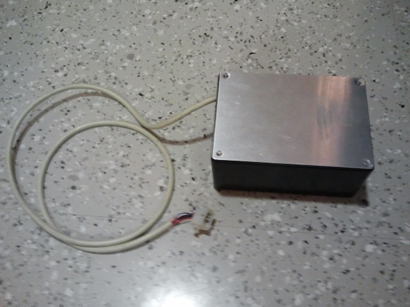
Put all of the components into a project box.

Make sure Arduino code is uploaded into the Arduino.

Plug the Molex connector into one of the Hillrom-8400 ports and power up the Arduino.

Load finished iPad application onto an iPad and connect to WiFi.

Once the red light on the WiFi Shield has lit up, the Arduino is connected and you should be able to control the bed from the iPad!