


OpenSCAD is an open source solid software modeler that allows you to use a declarative format to specify the shape of the object that you want to create. As a programmer, I find this so incredibly exciting that I got into 3D modeling since it lets me declare my objects in a familiar fashion. I have always been interested in procedurally generated objects; these are shapes that are created by using an algorithm that contains a random element in it. When I started using OpenSCAD, I realized that it was expressive enough to be a good tool to create them.
We are going to create a maze using a procedurally generated algorithm that is feasible to 3D print. Mazes have been studied for some time, and there are many variants of the algorithms that create them. Each has a specific look and we can generate different permutations for each one. We are going to do a binary tree maze, it is one of the simplest but it has a pretty distinctive look. The result can be used for a pendant or to try and pass a ball through it.
Let’s get started. The first thing we need to do is figure out how to get a random number in OpenSCAD. We use the function rands, which will give us a list containing random values. The code below gives us 10 values, each between 0 and 4.
randomValues = rands(0,4,10);
With this we are able to create a unique permutation of our maze in every run. I normally use the values as integers but random brings floating points, so we are going to be using the function floor(number) to lose the decimal point.
Our algorithm is going to consist of the following: we are going to create cells and those cells are going to have four walls. We are going to go cell-by-cell and we are going to only add the upper or the left wall. This will create a maze from end to end.
The first thing we need to do is determine the dimensions of our maze, the size of our cells and walls. We are going to declare this on the top of our script.
NumberOfCellsInX = 10;

NumberOfCellsInY = 10;

SizeOfTheCellInX = 2;

SizeOfTheCellInY = 2;

HeightOfTheCell = 1;

HeightOfTheWall = 3;

WidthOfTheWall = 0.1;
With that done we want to render the cell so we can see how one of them looks. It’s important when doing algorithms like this one to create them step-by-step and test them out so we know how it behaves. To render it we are going to use five cubes — one for the base and one for each wall.

//This is the cell

cube([SizeOfTheCellInX,SizeOfTheCellInY,HeightOfTheCell]);

//This is the bottom wall cube([SizeOfTheCellInX,WidthOfTheWall,HeightOfTheWall]);

//This is the top wall

translate([0,SizeOfTheCellInY -WidthOfTheWall,0])cube([SizeOfTheCellInX,WidthOfTheWall,HeightOfTheWall]);

//This is the left wall

cube([WidthOfTheWall,SizeOfTheCellInY,HeightOfTheWall]);

//this is the right wall

translate([SizeOfTheCellInX - WidthOfTheWall,0,0])cube([WidthOfTheWall,SizeOfTheCellInY,HeightOfTheWall]);
Now that we have drawn the cell the next thing that we need to do is place the cell into a module so that we can reuse it. Since we know that we are going to need the ability to turn walls on and off, we are going to pass into this module the ability to tell us which wall is on or off. We are going to do it by passing 4 Booleans values to the model: Top, Left, Right, Bottom. Below is an example of the module signature and the how the code looks for the bottom wall.
module cell(top,bottom,left,right)

{

//This is the cell

cube([SizeOfTheCellInX,SizeOfTheCellInY,HeightOfTheCell]);

if(bottom)

{

//This is the bottom wall

cube([SizeOfTheCellInX,WidthOfTheWall,HeightOfTheWall]);

}

//Add if statements for the rest of the walls

}

//This is how we call it

cell(true,true,false,false);
Above we test it by calling the module without the two side walls and we end with the following result.

At this point our individual cells are ready. We already know how to get random values. In the next step what we need to do is to actually make the maze have the amount of cells that we indicated at the start. To do this we are going to use loops with the dimensions from the start to translate operation and calls to the cell module.

//This code replaces where we had the test cell

//We are printing the grid in X

for  (i = [0:NumberOfCellsInX-1])

{

// The grid in Y

for  (j = [0:NumberOfCellsInY-1])

{

translate([SizeOfTheCellInX*i,SizeOfTheCellInY*j,0])cell(true,true,true,true);

}

}
We have a complete grid, which is pretty exciting! All we need to do now is select the correct walls to be drawn and they will be set. I will do it using the smallest possible grid and then grow it to size. The first thing we need to do is generate the number of random values we need. We are going to use the same call from the beginning and the number we need is the number of cells in the maze since we are only controlling whether we don’t draw either the left wall or the top wall. We only need one value to pivot.
// We get numbers from 0 to 1.9999

// Will be 1's and 0's when we use floor and we are multiplying by the number of cells

randomValues = rands(0,2,NumberOfCellsInX * NumberOfCellsInY);

….

//Inside the loop we change the call of the module to be

// The comparisons added on left and top add walls to the maze

translate([SizeOfTheCellInX*i,SizeOfTheCellInY*j,0])cell(floor(randomValues[i*j]) == 0,false,floor(randomValues[i*j]) == 1,false);
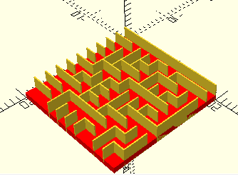
At this point we are done with our maze and every time that we render we get a different one. A common task after this step is to add a wall around it or a hook to make it a pendant. Both of these are fairly simple tasks, so I’ll leave them as an exercise to the reader. You can end up with many different variations by changes the sizes and dimensions of the maze and playing with the settings.


