File this one under the “What would you 3D print?” category. 3D printing really is all about you: your interests, your dreams, and your vision. The tools to design and make anything are closer than ever.
To show you what one person can do, this month I’m turning the keys to the blog over to Nick Chwalek, a 3D Systems senior sales manager, mechanical engineer, RC enthusiast, and maker. Let’s see what he’s formulating in his workshop.
_________________________________

I consider myself a simple man. I like the smell of bacon cooking on a Saturday morning. I like a nice cup of coffee and kittens and grassy fields. And I like an RC quadcopter that fits my exact specifications. Is that asking too much? I didn’t think so.
Being a gentleman of the maker persuasion, I’m in a pretty good spot. My job at 3D Systems gives me the 3D tools to tinker at a high level. The highest level, really, considering we’ve got scanning, design, and 3D printing right here. I’m a lucky guy. So when my quadcopter started to show some of its design flaws, I took to a Batcave’s worth of equipment around here that’s just waiting to be used.
Design Flaws
There were a couple of issues with quadcopter design that kept me up at night:
- At the end of each boom, where the motor mounts, there is a thin section. The motor mount section is actually thinner than the rest of the boom and has no support. As a result, during a hard landing (I never claimed to be a particularly good pilot), the leg would snap right off.
- Those perpendicular legs that stick out at the end of each boom support the quadcopter during landing. But the original legs were only about an inch and a half long, plenty long to land the quadcopter normally. But I’m also a sucker for aerial photographs, and if I wanted to mount a camera under the quadcopter, these short legs didn’t give me enough clearance to land, unless I wanted to land on the camera.
The Fix
Now, I know what you’re thinking, and, yes, I did consider a whole load of duct tape. But that wouldn’t give me the warm fuzzies like a redesign with pretty 3D printed components. Besides, a redesign would be a good learning experience with the software that I sell.
I started by scanning the original boom, which I had no problem with otherwise, and working from a model based on that scan data. The original sidewall of the boom was about .375 in. tall all the way across (with a rounded edge at the bottom) until you reached the motor mount, where it suddenly dipped to about .1875 in.


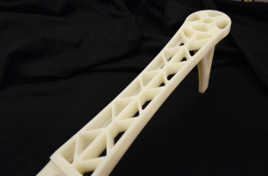
My redesign added thickness to the boom overall. I also squared off the edges and tapered the sidewall length from the body side of the boom down to the leg. The redesigned boom starts at about .5625 in. thick by the body and slowly tapers down to about .375 in. thick by the leg. The leg side is much stronger than it was at only .1875 in. No more snapped legs. Smiles. Kittens rejoice. Cured meat for everyone.
Now on to the leg length issue. I did a couple of things here. First, I made the leg longer, almost doubling the overall length from 1.875 in. to 3.5625 in. But I also added some extra strength by thickening the legs pieces and crossbar by .125 in. each, and I moved the crossbar so it’s parallel to the ground. I wanted to make everything thick and burly, as you can see. That way the risers would be able to withstand the stress upon impact with the ground.

3D Printing and Fitting
To manufacture the piece, I went with the 3D Systems ProJet® 6000, which is a high-definition crossover SLA (Stereolithography) 3D printer that’s easy to use in an office environment. It took around 15 hours to complete the print, and it looks amazing. Perfect detail and a nice smooth surface finish. Now if I could just get one of those bad boys for my home, I could start my own RC vehicle company.
Bolting the boom onto the chassis was essentially uneventful. It fit perfectly the first time without any modification, hammering, tooth grinding, cursing or anything of the like. So I’ve got the first of four stronger quadcopter booms, which will provide plenty of clearance for a gimbal or rigid-mounted camera on the bottom.
And that makes a simple man like me happy. Now, if I could just find some bacon around here.
ADVERTISEMENT


