YouTube player

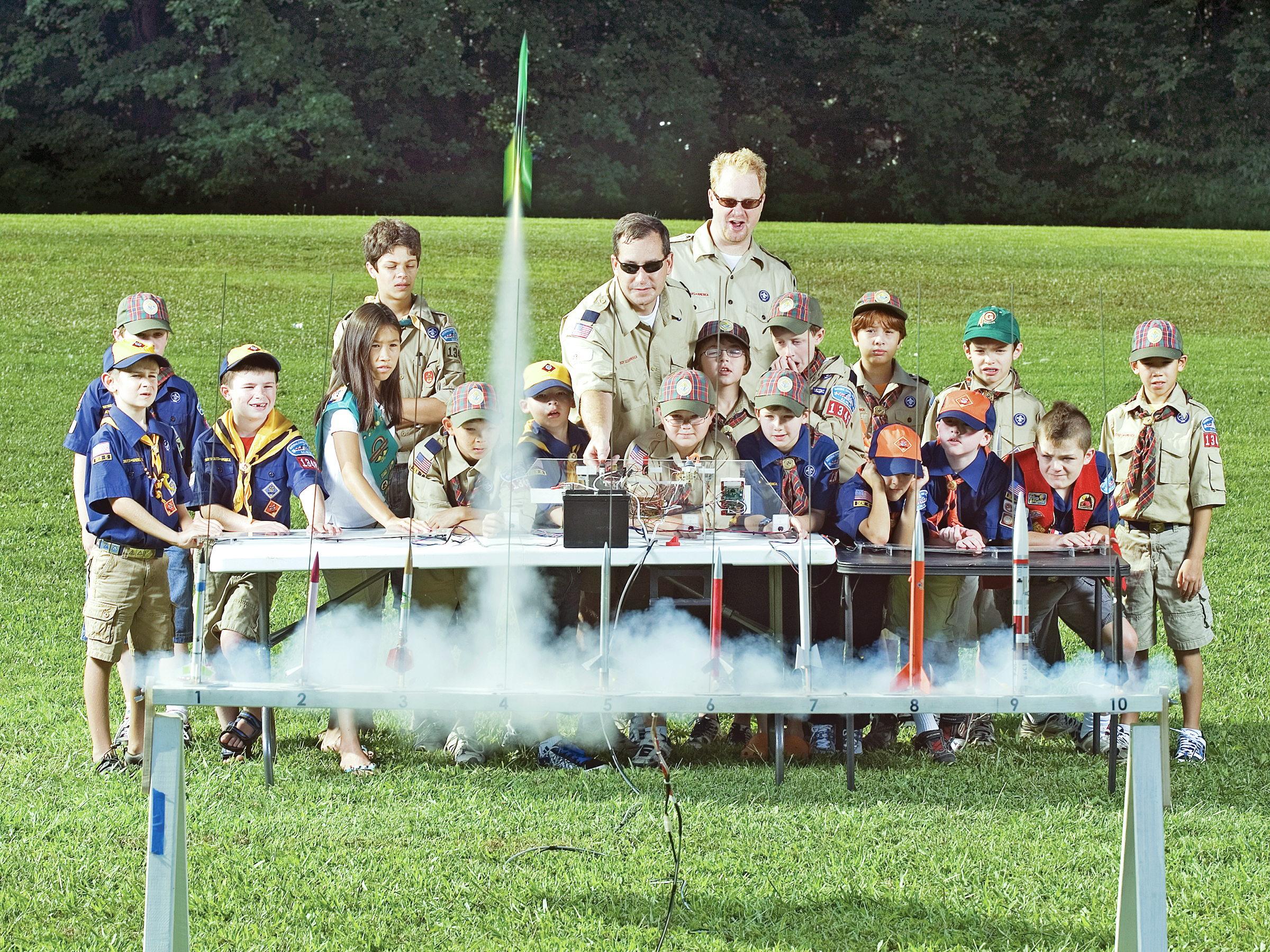
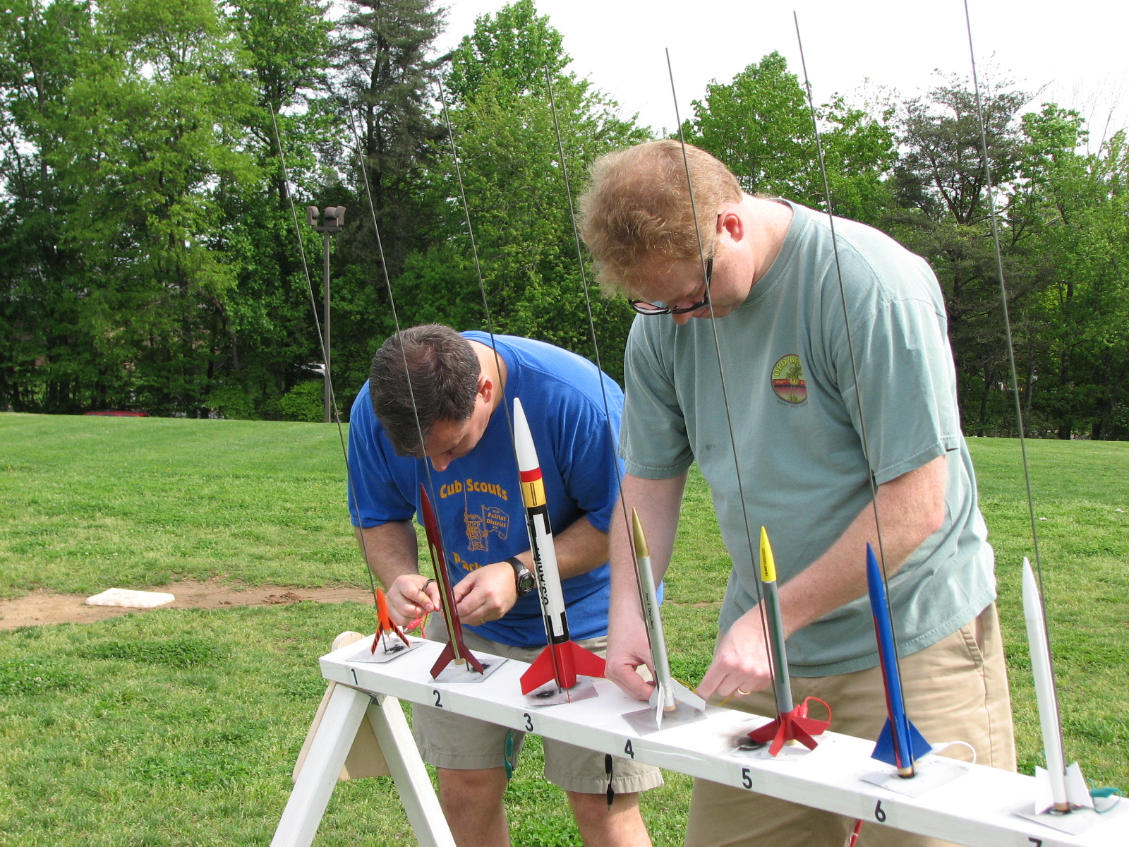
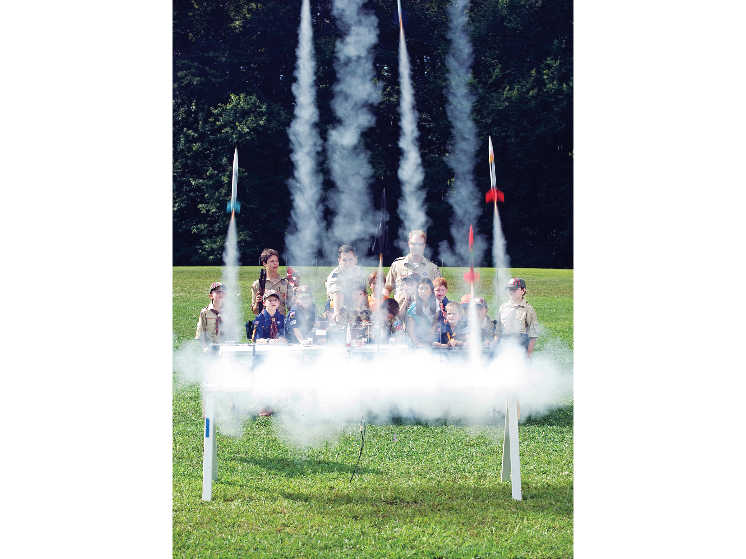
At last year’s annual Cub Scout Pack 1346 rocket derby, nearly 100 rockets were launched, testing the attention span of many younger scouts. For this year’s event I wanted to build a system that would create more excitement and keep the pace of the launches moving along. This 10-pad mega-launcher is the result of that initial inspiration.

This system gives kids the fun of pressing their own launch buttons, and for added drama, sounds a klaxon before each launch. For the finale, a “Mega Launch” switch shoots off all 10 rockets at once.

I also wanted to minimize the chance of an unfired rocket left on the pad while the others soared skyward, disappointing a child. Therefore, this system has always-on igniter continuity checks, using LEDs to show which igniters are ready. Blocking diodes allow dual-use of the wire harness — for continuity check and launch voltage — thus halving the number of wires to the launch bar.

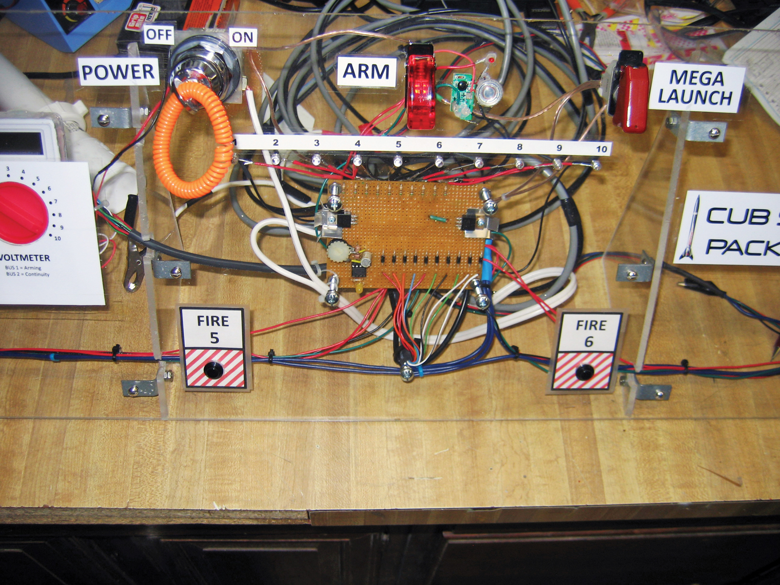
The system also needed to withstand rough handling from lots of kids, so I used copious amounts of hot glue, heat-shrink tubing, and zip ties. And along the way, another goal became showing the kids that a system like this isn’t complicated, which is why I put the workings behind clear plastic.

What will the next generation of Make: look like? We’re inviting you to shape the future by investing in Make:. By becoming an investor, you help decide what’s next. The future of Make: is in your hands. Learn More.

Project Steps

Layout

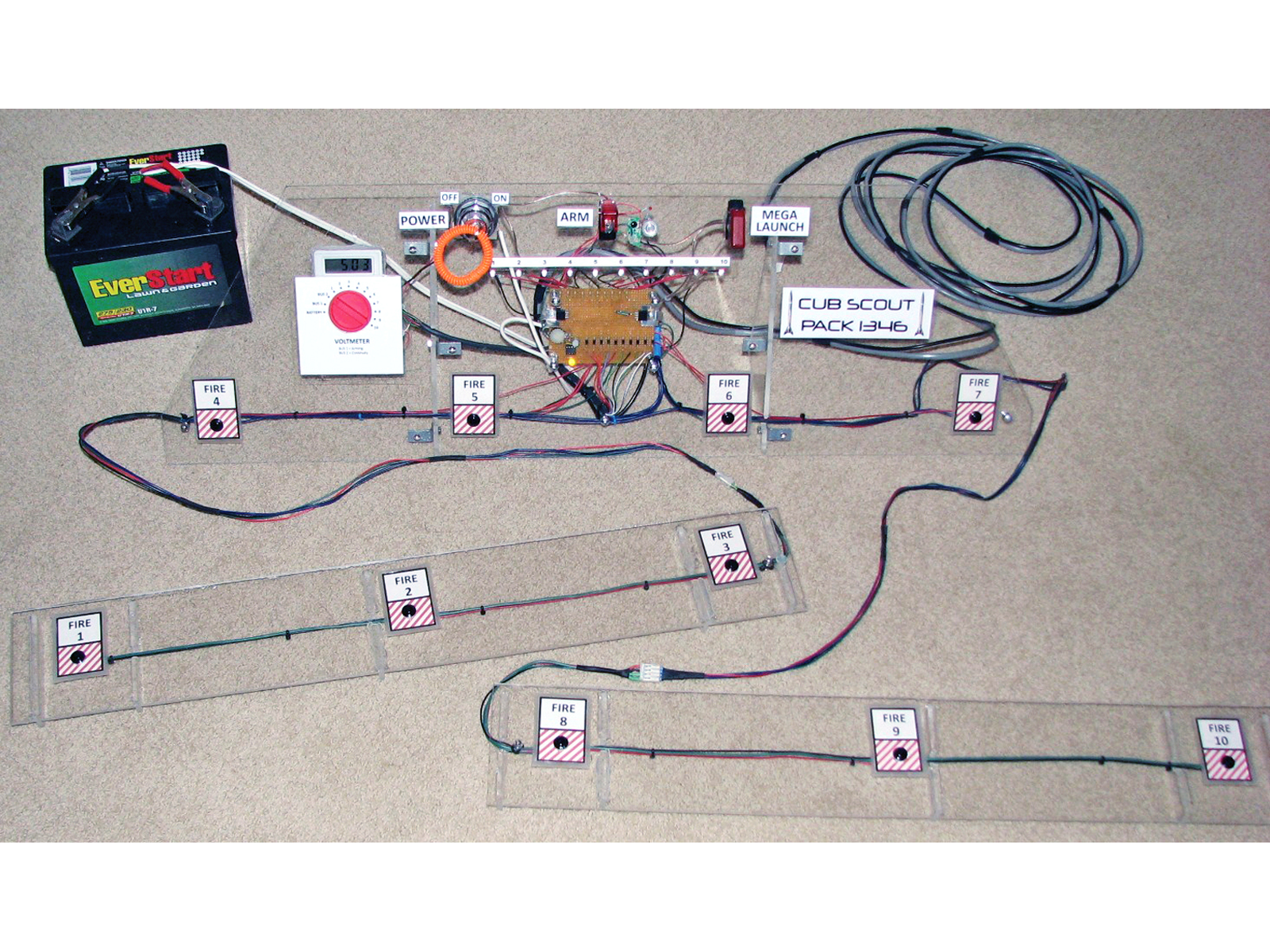
The mega-launcher consists of a 10-rocket launch bar and its control station connected a safe distance away by a 25′ cable. The control station fits on 2 long folding tables arranged end to end, with firing stations 1–3 on the left, 8–10 on the right, and 4–7 on the control console in the middle.

The console carries the system-wide Power, Arm, and Mega-Launch switches. For safety, the main power switch on the control console is a key switch; this lets you pull the key to prevent overly excited scouts from firing rockets while someone is still working at the launch bar.

Turn on the power, and a row of 10 continuity LEDs tells you which launch pads have igniters in place that are ready to fire. Flip up the Arm switch and the klaxon sounds, signaling that the firing station and Mega Launch buttons are now enabled!

Circuit Design

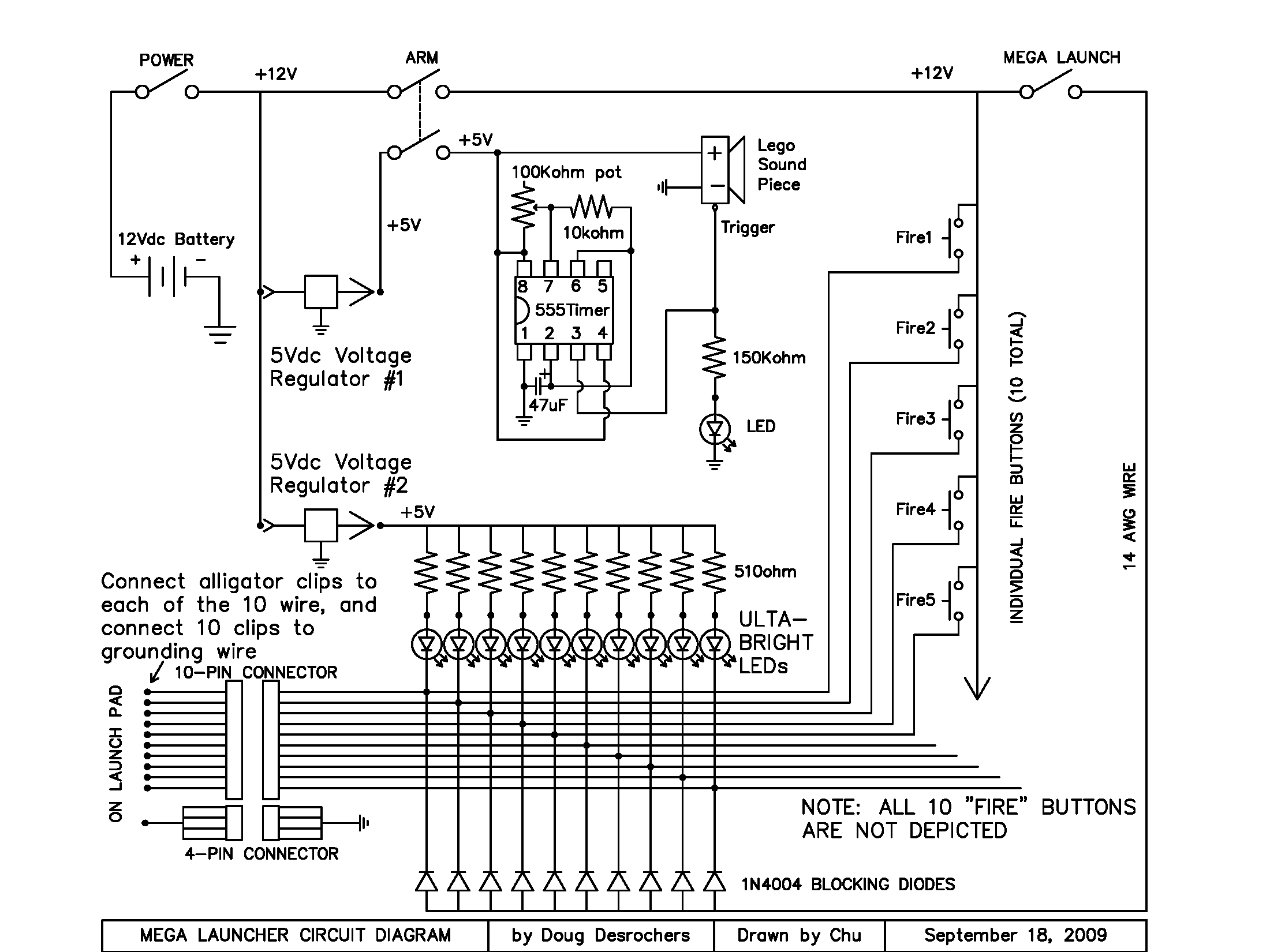
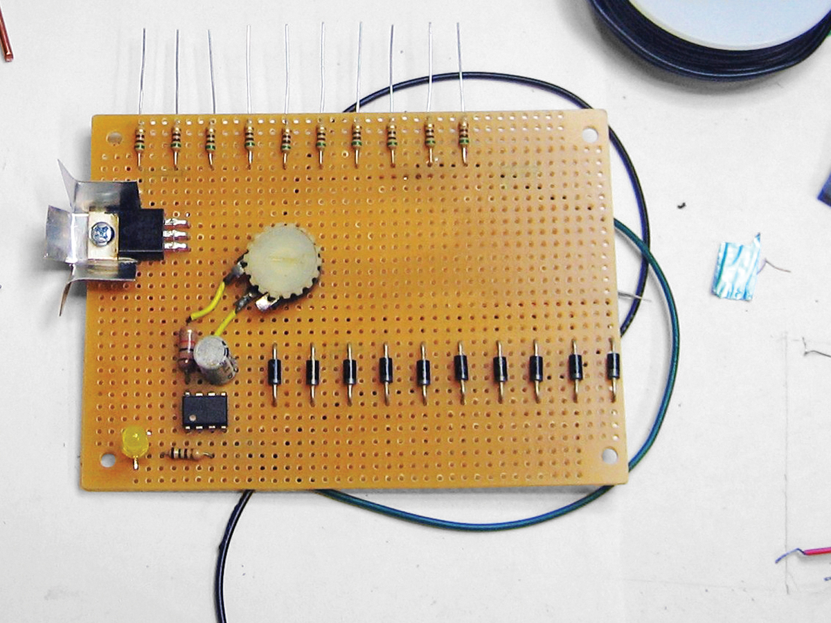
The system is powered by a 12V battery, and continuity to each igniter is ensured by an LED that’s bright enough to see in daylight. To accomplish this, the circuit constantly trickles 5V through each igniter in series with the LED and a 510Ω resistor. Pressing a firing button overrides this series and delivers full voltage to the igniter.

This is the neat part of the system; one DC wire running to the launch bar serves as both the continuity check in one direction, and provides firing 12V DC current in the other direction when the firing button is pressed. See the circuit schematic at left. Naturally, I went through a number of test igniters before I found component values that would keep the LED lit but did not spark the igniter.

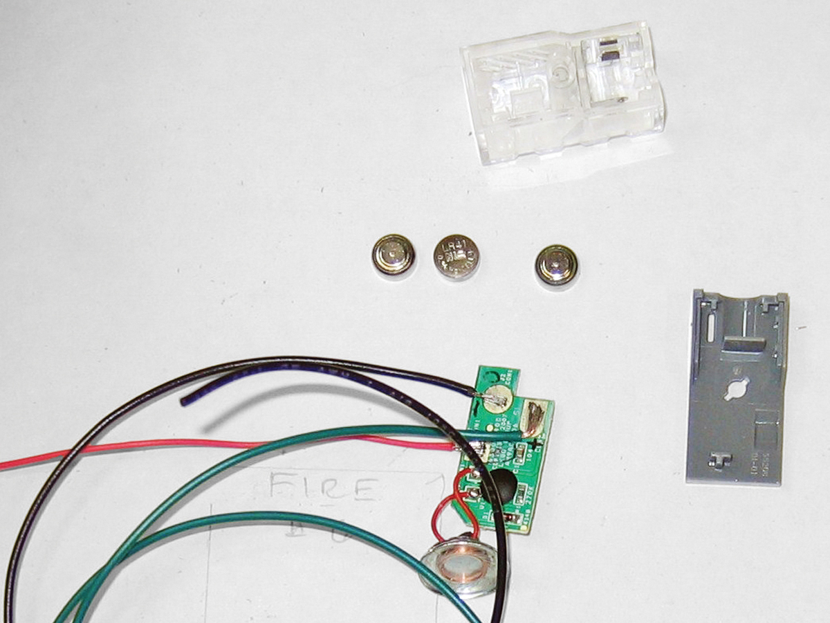
I included the alarm, which sounds when the system is armed and the rockets are ready to fire, for both fun-factor and to give adult supervisors some warning to get everybody away from the launch pads. The Lego sound brick I used only sounds 5 klaxon “beeps” per triggering, so I added a pulsed trigger circuit based on a 555 IC chip to extend the duration of the alarm and make it adjustable with a 100K potentiometer. I also added a yellow LED and 150Ω resistor that indicate when the 555 chip is triggering.

The circuit has two 5V DC voltage regulators because the peak draw of the continuity LEDs is 100mA and the regulators are rated to 1A. With a 10-pad system, this means dedicating one regulator to the LEDs and using the other for the alarm.

Electronics

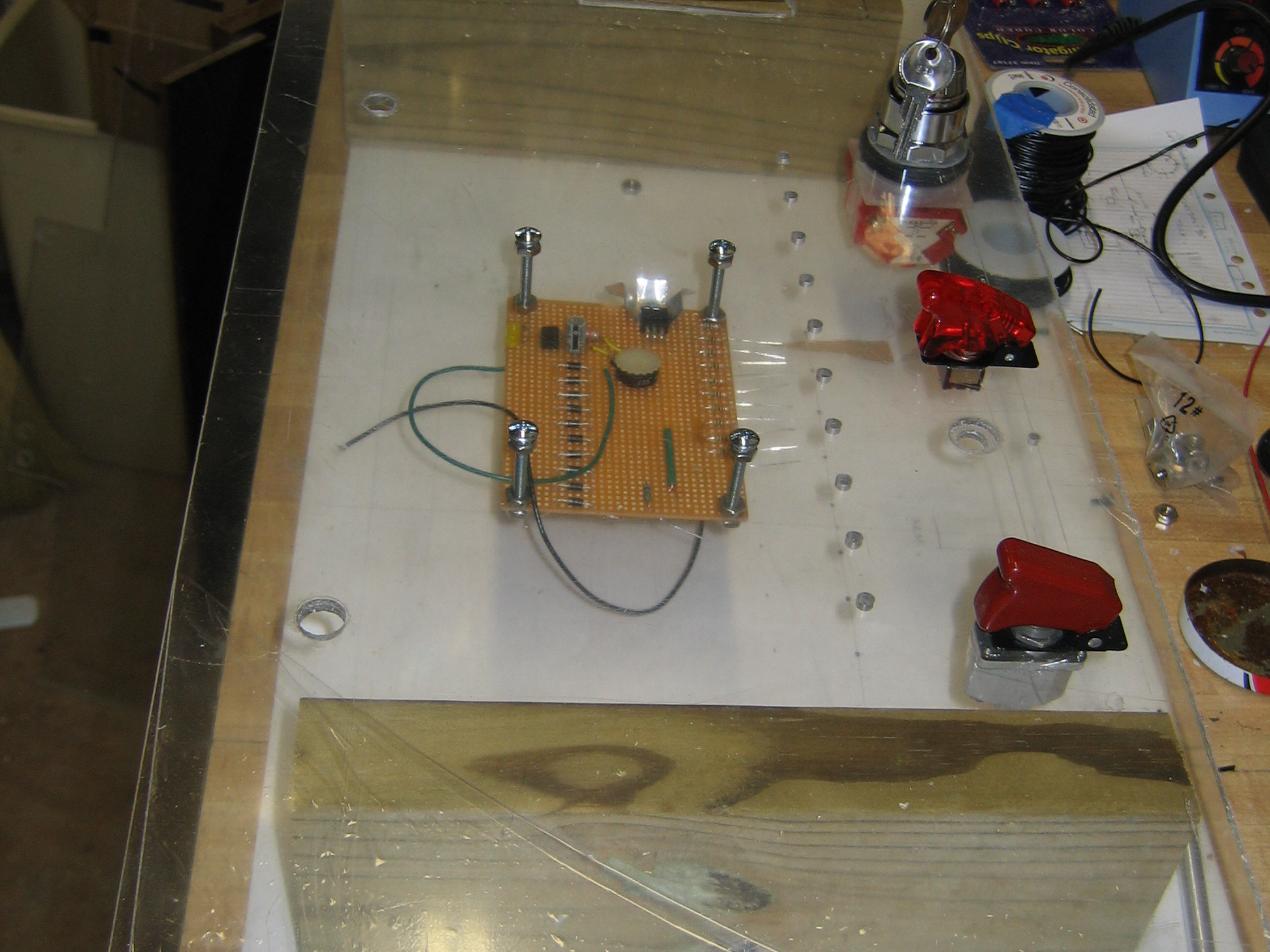
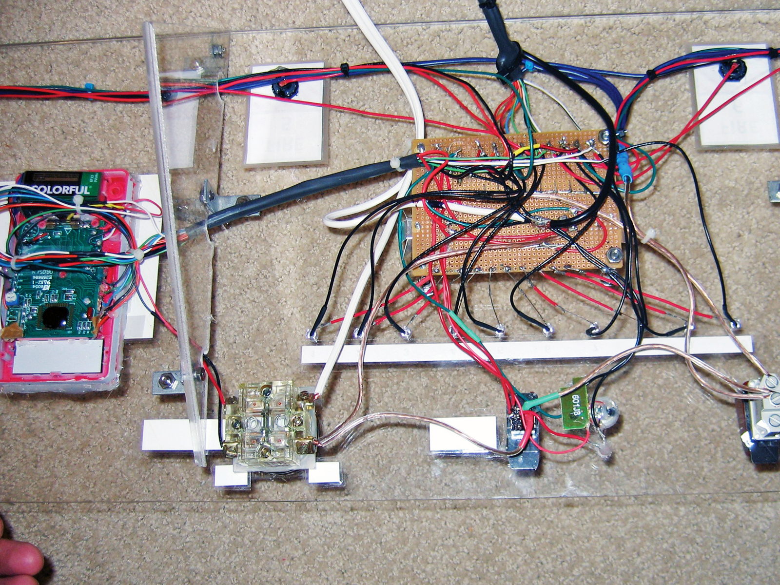
I built most of the control circuitry on a piece of perf board, separating the components to allow plenty of space in back for the power and ground connections. I mounted the circuit board just behind the Lexan control panel using 1½” pan head screws, so you can see all the components up close but they still have breathing room.

I mounted the switches, LEDs, and alarm speaker in the Lexan panel, drilling LED holes with a #9 bit and larger holes with a Forstner bit. The Arm switch is a double-pole switch, and I used a military aircraft weapons switch for the Mega Launch function, but any SPST will work.

I arranged the 510Ω resistors that lead to the continuity LEDs along the top edge of the circuit board, allowing short connections to the row of LEDs in the panel just above. To connect the alarm, I disassembled the original Lego brick, soldered leads to the mini board inside for trigger voltage and ground, and spliced in 2 more wires to bring the speaker off-board and let it reach the panel.

Panels and Wiring

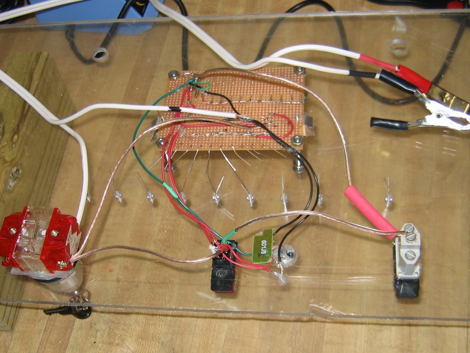
The central control panel is built into a 36″×11″ Lexan panel with two 9″×6″ triangles cut from the top corners and reattached with angle brackets to make a standing base. The 2 side firing panels were built into 5″×30″ Lexan strips, each connected to the console by a 4-pin harness. I used small zip ties to bundle wires together throughout. Be sure to check the switch wiring with a voltmeter prior to soldering.

Power for the system comes from a big 12V battery that sits behind the control panel. With a full charge, this 230-cold-cranking-amps battery lasts well past 200 ignitions. To connect it to the circuit, I used lamp cord and medium-sized clamps to grab the battery terminals.

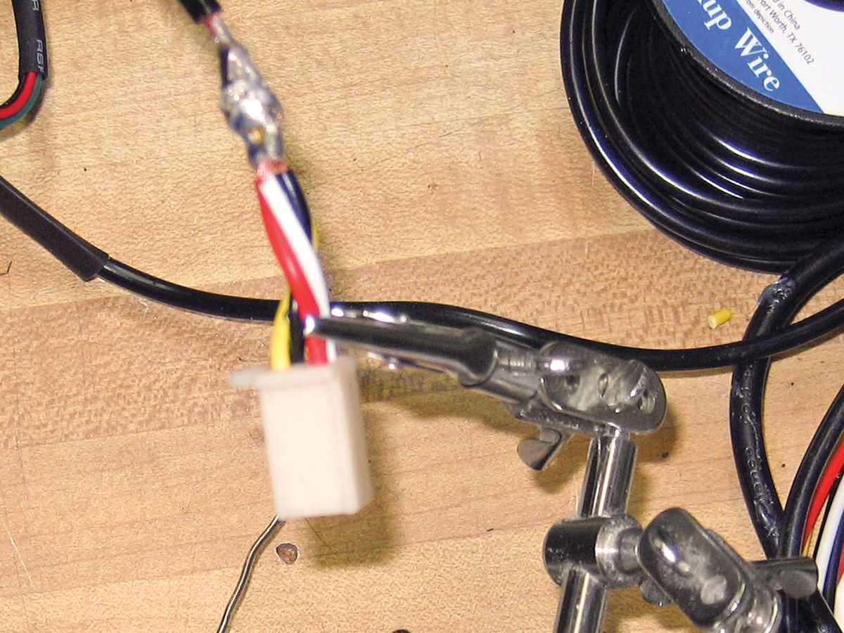
For easier storage, I used a 10-wire connector for detaching the cable to the launch bar, and two 4-pin connectors (3 launch, 1 ground) for disconnecting the wire bundles leading to each side launch panel. The 14-gauge launch bar grounding cable also detaches via a 4-pin connector, in order to prevent a current bottleneck at the disconnect point.

Connecting four 22-gauge ground wires, all soldered together in parallel to the heavy grounding wire, splits the load.

Launch Bar

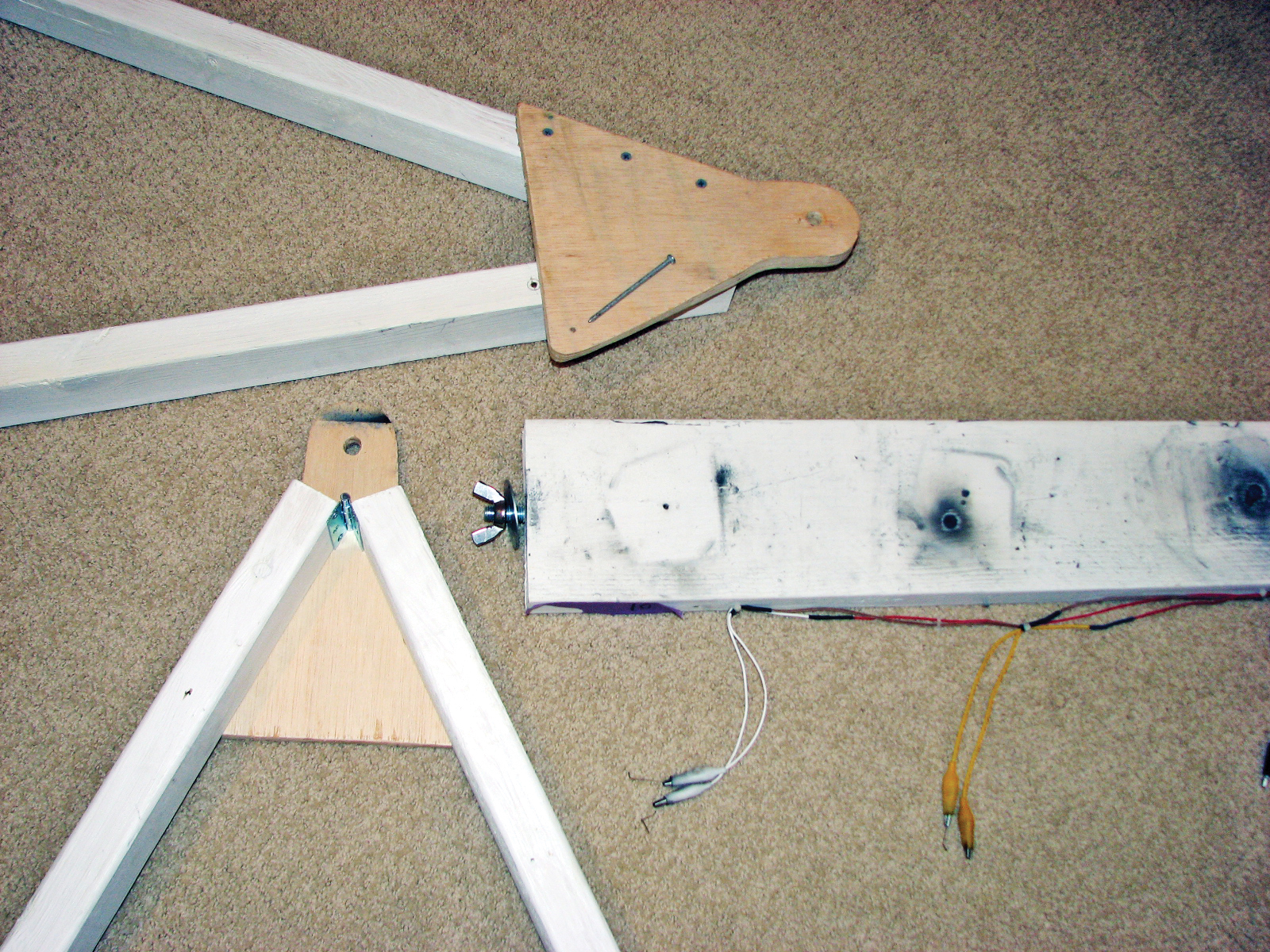
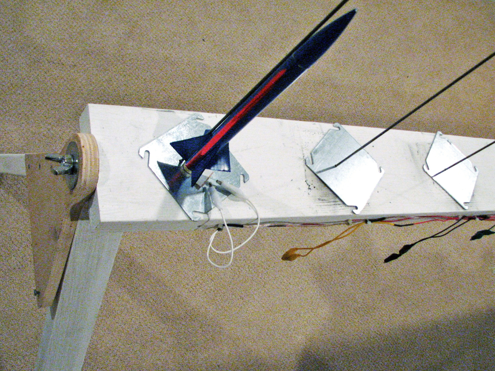
The launch bar is straightforward. To elevate it, I built 2 foldable sawhorse legs using 2×3 lumber, a hinge, and a triangular piece of plywood. One side of the triangle is fixed to one leg with wood screws, and the other is drilled out for a removable nail, so the legs can be folded for storage.

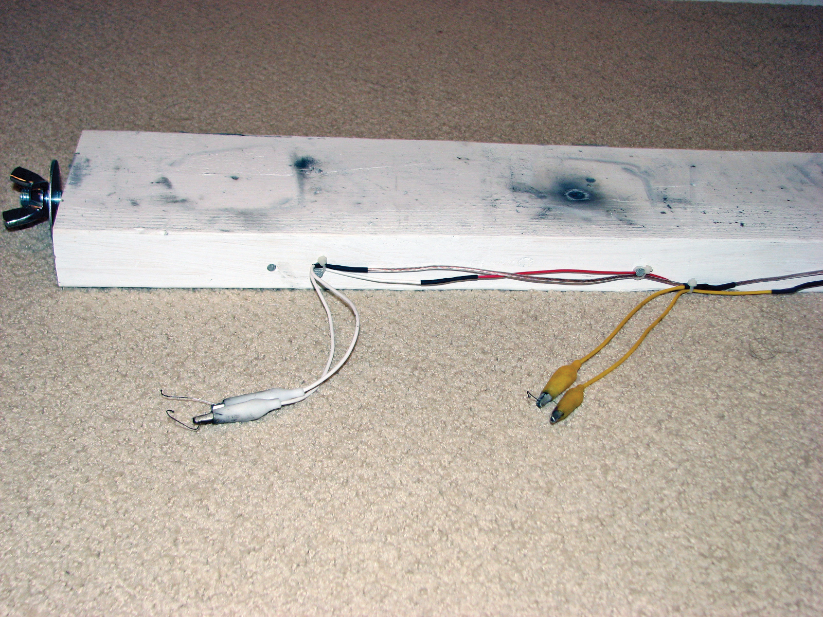
The launch bar itself is an 8-foot 2×6 board with 10 individual pads consisting of a metal outlet plate for the blast shield and a 1″×3′ steel rod for the launch rod. I used a drill press to set 1″ holes 9″ apart on the board for each rod, and drilled 6″ holes through the plates to let the rods pass through. You could use construction adhesive to glue the rods into the holes and glue down the plates, but I left them unglued for easy storage and transport.

To allow pivoting of the launch bar for wind adjustments, I cut the heads off 2 large 13mm bolts, then drilled the launch board ends and glued in the bolts. The bolts pass through holes at the top of each sawhorse triangle, secured with wing nuts on the other side.

Each station has a pair of mini alligator clips to clip onto the igniters, 1 for voltage and 1 for ground. To wire the voltage clips to the 10-wire cable in the middle of the bar, I ran a 22-gauge red wire from each station to a pin on the 10-pin connector. I used lots of heat-shrink wrap and zip ties, but after 210+ rocket launches, still wound up with 2 broken wires.

Wiring the igniters’ ground sides was a little more complicated. At the ground cable’s 4-pin connector, I soldered 4 strands of 14-gauge speaker wire, and then ran a short and a long strand to the left, and a short and a long strand to the right. I attached the alligator clips by soldering to the ends of the speaker wires where possible, or else soldering mid-wire after scraping away some insulation, then covering with heat-shrink.

Design Overkill

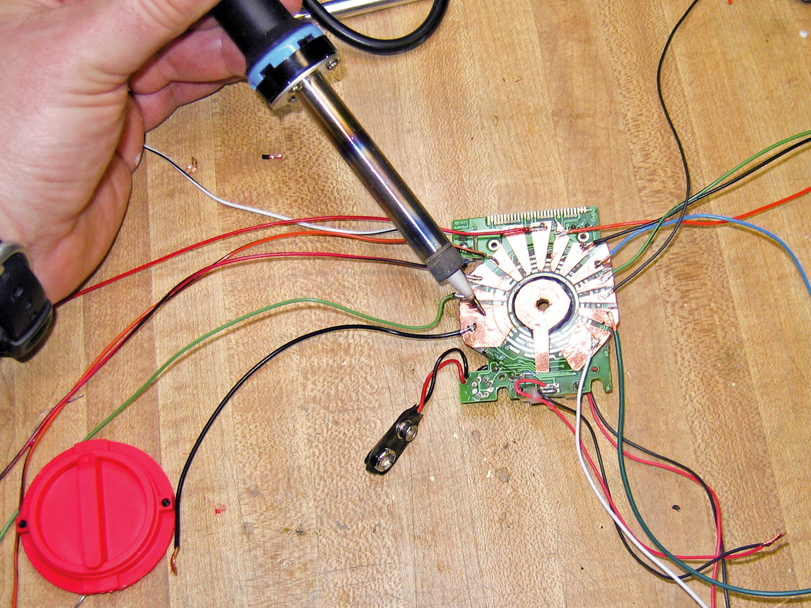
Eagle-eyed readers will note in the photographs an unexplained feature that falls into the overkill category. I hacked a multimeter to make a knob for the control console that you can turn to check that 12V DC is running across each of the 10 blocking diodes.

Long story short, I soldered jumpers to the multimeter board to keep it permanently at its 20V DC setting. Then I carefully cut and arranged copper tape traces on a thin plastic sheet to match the contact points of the multimeter’s knob. The traces connected to a wire bundle that tapped into the blocking diodes for each igniter. Turn the knob, and you can check each one.

This all took as much time to get right as the rest of the project, and after 180+ launches I realized that it represented almost no value added. I thought that seeing the actual voltage at each pad would help troubleshoot, but the continuity LEDs worked perfectly on their own, and saved many launches where there was a short circuit at the pad. You can also just use a multimeter to check the voltage across the battery before each launch.

Lessons Learned

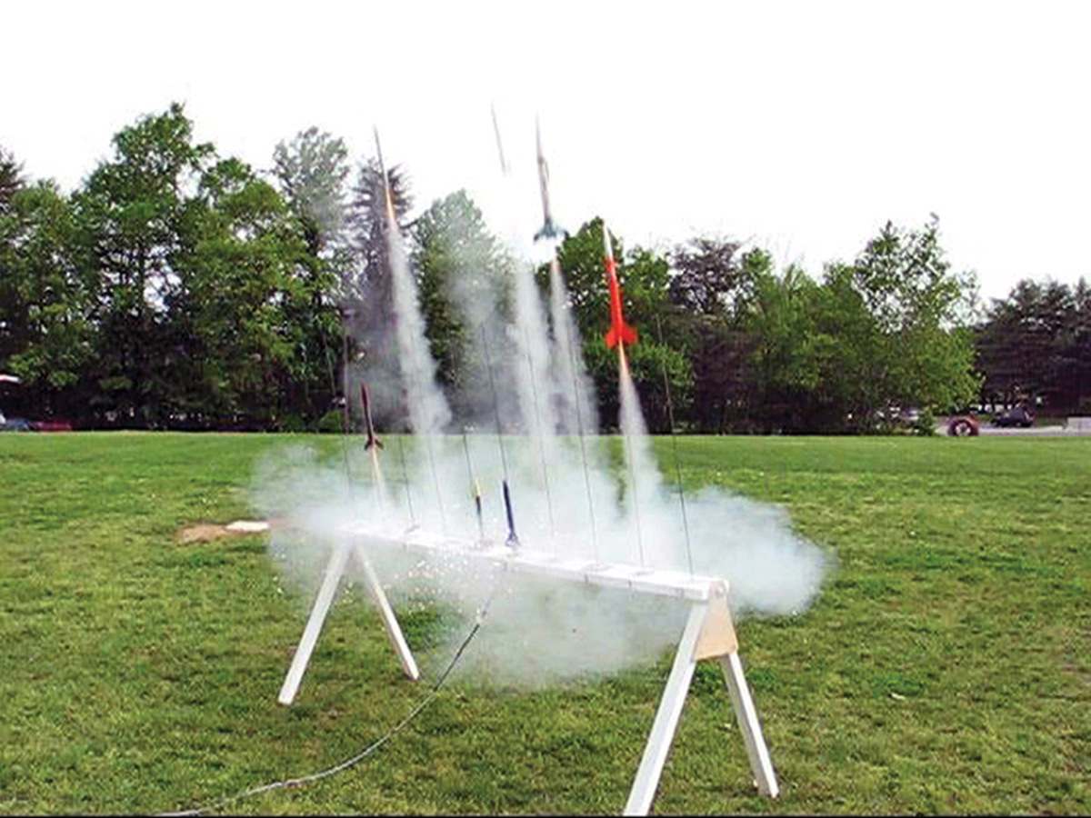
The mega-launcher made our Cub Scout Rocket Derby a blast. More than 120 rockets were fired in less than 90 minutes — a huge improvement over single-launch systems! And the klaxon sound was a big hit.

One lesson learned from the test launches is that with the close spacing of the rockets, about 9″, an adjacent liftoff could knock an igniter loose or cause the clips to short out. A few pieces of masking tape solved this problem.

Another thing we found: with so many rockets in flight at once, it was difficult to track all of them through touchdown!

Here is a video of the 10-rocket mega-launcher in action.

Conclusion

This project first appeared in MAKE Volume 20, page 60.