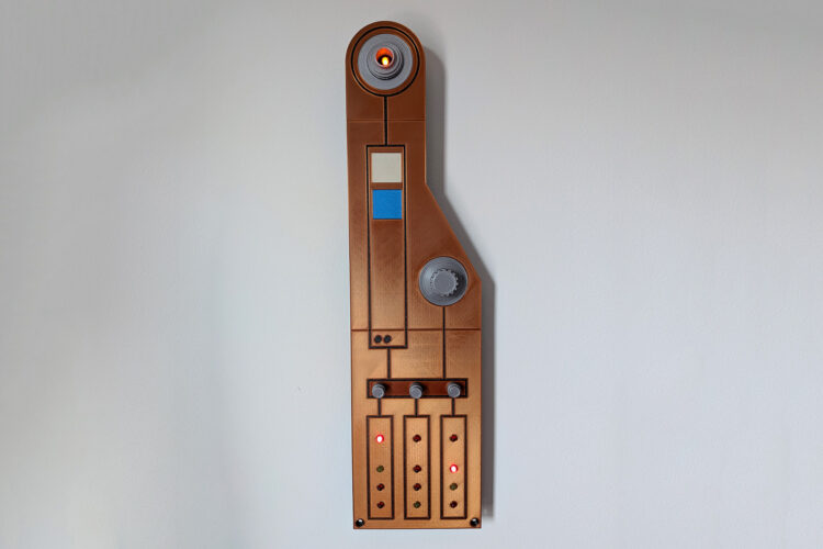







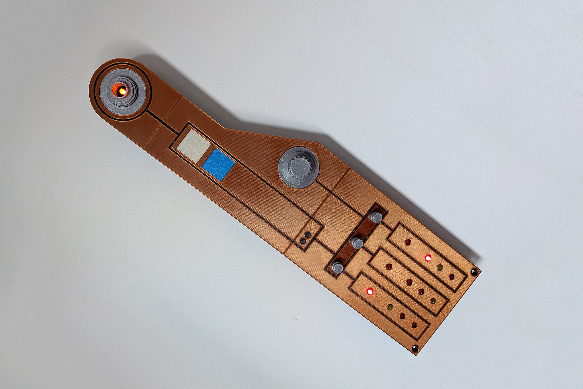


Decorate your own Rebel Hideout with a Star Wars set decoration, closely modeled after an actual prop from Luthen Rael’s workshop on Coruscant! This simple control panel project is the base for a larger electronics project; you can just connect the lights to a power source and switch, or you can use a microcontroller to read the potentiometers for interactivity (along with some shift registers if you want many panels) and really bring this prop to life!

The 3D print files include:
- Three base panel pieces (A, B, and C)
- One large knob
- Three small knobs
- Two light panel covers
- Four potentiometer spacers
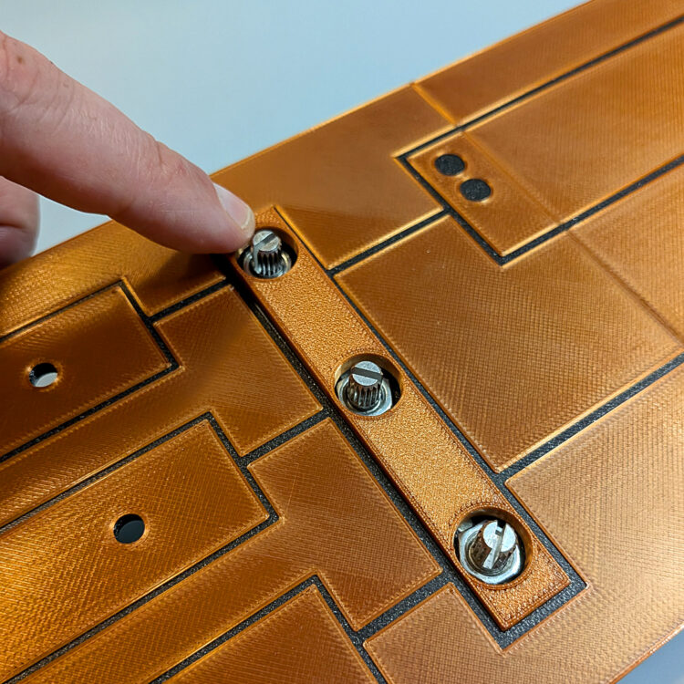
- One potentiometer cover
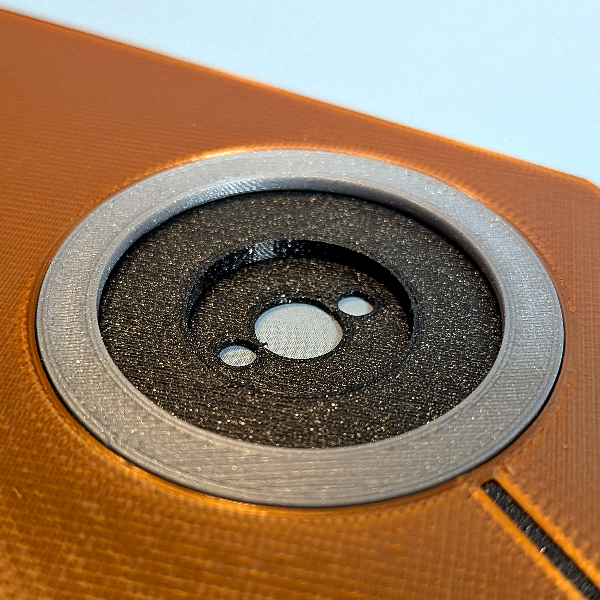
- Large ring greeblie
- Small ring greeblie
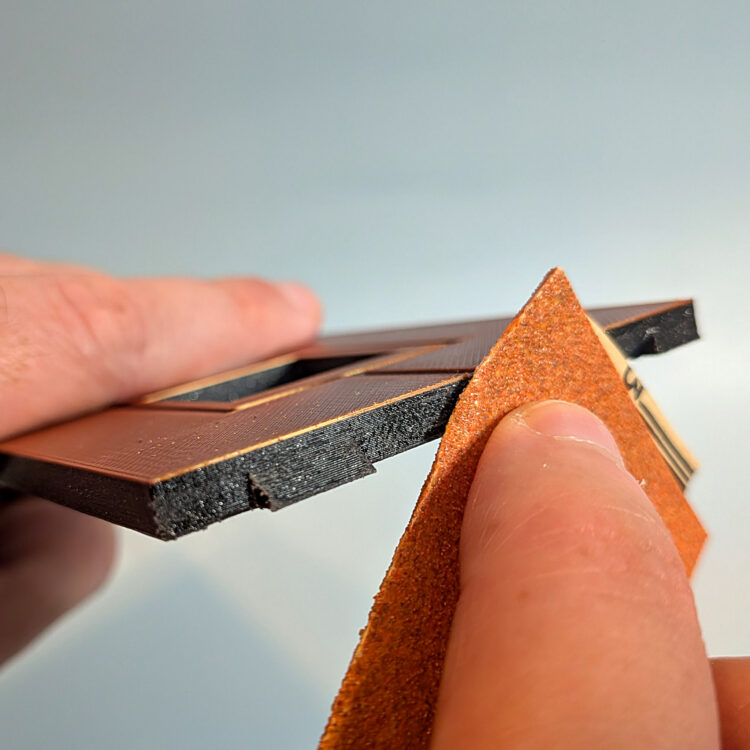
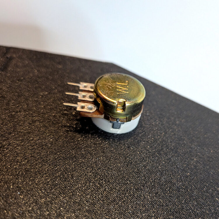
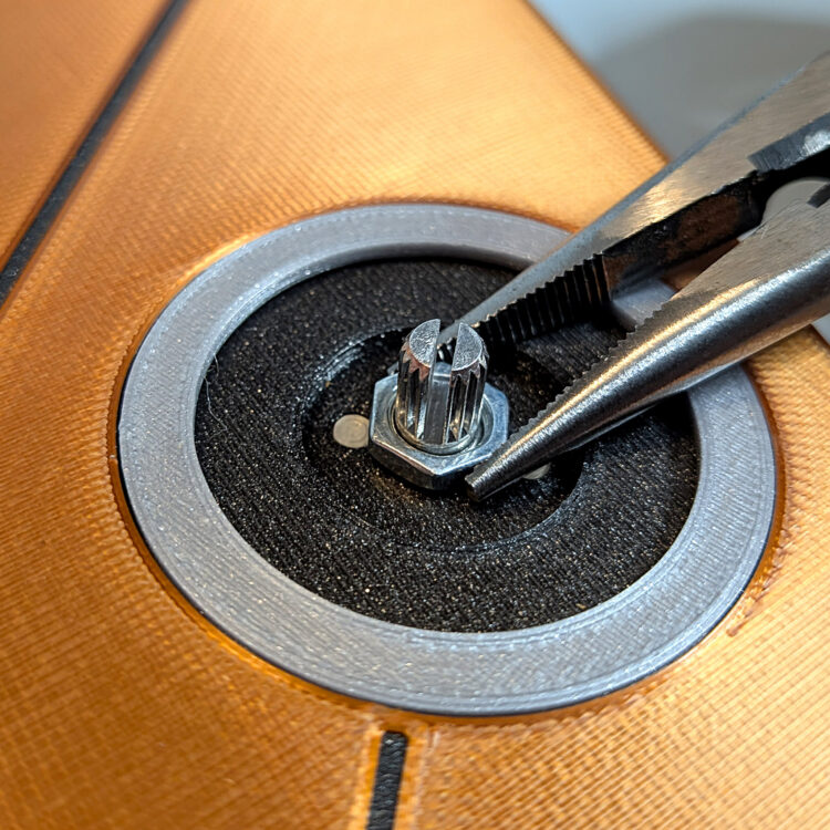
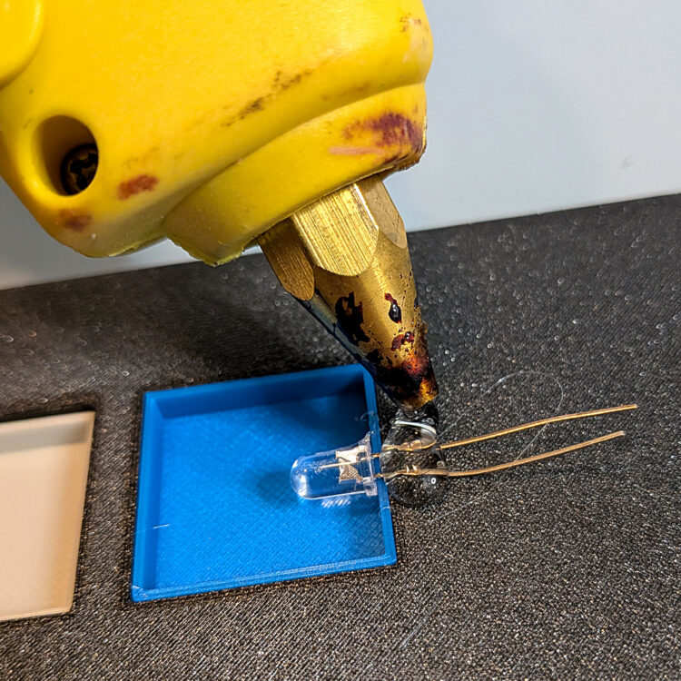
In addition to the 3D print files, all you need are 15 5mm LEDs, four 6mm potentiometers, super glue, hot glue, sandpaper, and a pair of needlenose pliers.
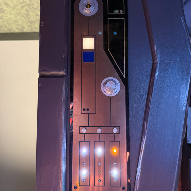
Luthen’s gallery in the Andor series, Galactic Antiquities and Objects of Interest, was loaded with Easter eggs from all parts of the Star Wars universe of films, TV, and video games. Build this project and your workshop will have a Star Wars Easter egg of its own.

Photo by Hayley Benoit, Lucasfilm

Printing Tips
This project was tested on a Prusa MK3S+, using a 0.15mm layer height. Tolerances may vary depending on your printer model and settings! Print files are initially separated into four build plates for simplicity; however if you want to match the color scheme in this tutorial which is more accurate to the source prop, I would recommend printing the smaller components as follows:
- Group 1: Potentiometer Cover
- Group 2: Potentiometer Spacers
- Group 3: Greeblies (2) and Knobs (4)
- Group 4: Light Panel Cover A
- Group 5: Light Panel Cover B
If you want to do a multicolor print for the panels but do not have a multi-material system, slicers typically have a function to allow you to add a pause for a filament color change. To do it in PrusaSlicer, right-click on the layer slider on the right side of the screen at the height you want to add the pause, and select Add Color Change. Consult your slicer’s documentation for more information!


Papercraft this panel!

No 3D printer? No problem! You can “kitbash” this same Star Wars prop from cardboard, caps, and scraps!
Mechanical engineer Crew Parker is Lucasfilm’s asset coordinator, so he knows all about TV and movie props. He created a version of this project you can easily make from stuff at home — cardboard and paper, hot glue and Elmer’s, a Sharpie marker, colorful pushpins, and some bottle caps and lids scrounged from the trash to create your own greeblies — plus a little silver and gold paint. You can even add electronics like LEDs and real pushbuttons if you want!