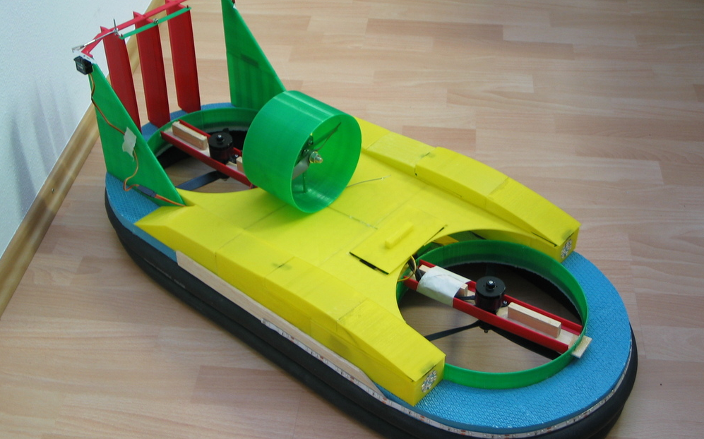
3D Printed Hovercraft

I got the idea to build this last year when I read an article about hovercrafts. After studying the topic further I wanted to build one for myself.

This is my third prototype. Previous versions were difficult to control and had a hard time carrying weight and keeping debris away from the lifting motor. I designed this using Autodesk Inventor 2013 and a MakerBot Replicator 3D printer. It took around 3–4 days to fully print the final design of the hovercraft.

DIY Hovercraft 3D Printed Hovercraft

The base is not printed because it would take way too long. Plus, Styrofoam has the advantage that it swims when the engines fail. I also did not print the bicycle tubes because they have to be flexible and they must be one piece so that no air flows out to the sides.

The Hovercaft is lifted by two motors and it has one thrust motor. The power for the motors comes from three 2800 mAh LiPo batteries.

My plans with the Hovercraft are to develop a cheap mobile research station for the arctic. The advantages are that it has no CO2 emissions and you can control it from a remote location, like a drone.

You can find the required STL files for this project on Thingiverse. The following steps will provide you with the information you need to assemble the printed parts, wire the electronics, and configure the R/C channels.

YouTube player

Project Steps

Cut shape in base

Use a hobby knife to shave off two half circles in the front and the back of the Styrofoam base, defining the rounded board shape.

Cut holes

Cut two holes for the lift motors. The holes should 9.6 inches in diameter and be placed 2.3 inches away from their respective edges.

Print parts

Print all parts, making a note that there are multiples of several parts.
– 2x Ruder 2.1
– 2x Ruder 2.2
– 3x Ruder
– 1x Ruder 4.1
– 1x Ruder 3
– 1x Schubmotor

– 3x Akku
– 1x Verdeck
– 1x Stuetze
– 1x Verkleidung 1.1.1
– 1x Verkleidung 1.1.2
– 1x Verkleidung 1.1.3
– 1x Verkleidung 1.2.1
– 1x Verkleidung 1.2.2
– 1x Verkleidung 1.2.3
– 1x Verkleidung 2.1.1
– 1x Verkleidung 2.1.2
– 1x Verkleidung 2.1.3
– 2x Verkleidung 2.1.4
– 1x Verkleidung 2.2.1
– 1x Verkleidung 2.2.2
– 1x Verkleidung 2.2.3

– 2x Ring 1
– 2x Ring 2
– 2x Ring 3
– 4x Halterung
– 2x Hubmotor or 2x Verkleidung 2.1.4.1 and Verkleidung 2.1.4.2

Glue

Glue with hot glue the parts “Ring 1, 2 and 3” into the holes and let it dry.

Afterwards take “Hubmotor” and glue it with two-part epoxy into the slots. Glue “Halterung” onto the “Hubmotor” with two-part epoxy.

Assemble boost motor

Attach the “Schubmotor” print to the Pichler Motor.

Attach the propeller included with the motor to the motor shaft.

Now glue the assembled “Schubmotor” with hot glue in front of the back lift motor.

Large rudder assembly

Take “Ruder 2.1 and Ruder 2.2” glue them together and then on the base.

You can glue the rudder and the lift motor ring together.

Small rudder mounting holes

On the back of the base, use a pencil to push three holes for the rudders to mount in and glue a washer on each hole to reinforce it.

Small rudder assembly

Now take the “Ruder 3” and glue it on top of the large set of rudders on the sides.

Push the three smaller rudders into position.

On the right rudder drill out a small hole to allow you to glue and slot-in a length of steel pin which will later attach to the servo.

Linking rudders

Take “Ruder 4.1” and use it to link the smaller rudders together.

Glue the servo into place on the large right rudder.

Connect the servo arm to the pin on the smaller right rudder using another length of steel pin or a pin fastened to the servo with a nylon clevis fastener.

Create upper structure

Take the other parts and glue them on the base following the diagram.

Using Velcro will allow you to temporarily place parts that you may wish to open or modify later.

Place headlights

Glue the front 11.1v headlights into their position.

Position battery holders

Glue the “Akku” LiPo battery holders into position so that the weight of the battery balances in the middle of the Hovercraft. One “Akku” is under “Verdeck” and the other two are on the sides.

Inflate and glue tubes

Turn the Hovercraft upside down and glue the bicycle tubes under the base.

Connect ESCs

Connect all ESCs to the motors. You have to cut two of the three red cables of the ESCs because the receiver needs only one power cable.

My receiver configuration:
– Thrust -> Boost motor
– Rudder -> Rudder
– Aileron and Elevator ->Liftmotors (Hacker brushless)

On the transmitter choose the mode: Elevon Wing Type Connection. You can cut holes in the cover for the cables.

Make it your own

Put more lights on your Hovercraft, like this multi-color LED strip.