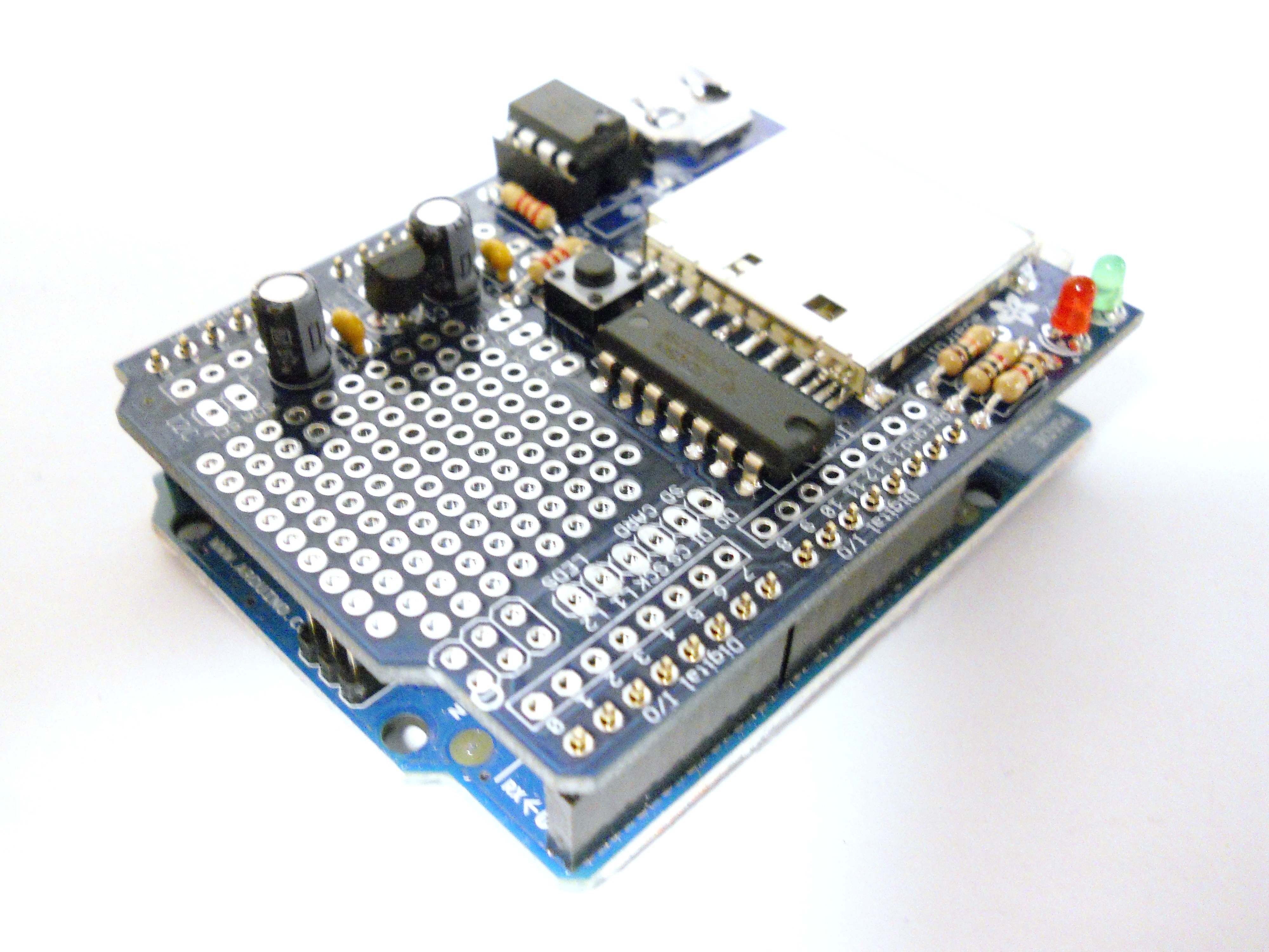
This data-logging shield for the Arduino makes saving data to files on any FAT16 or FAT32 formatted SD card really easy. The included Real-Time Clock timestamps all your data with the current time, so that you know precisely what happened and when!

What will the next generation of Make: look like? We’re inviting you to shape the future by investing in Make:. By becoming an investor, you help decide what’s next. The future of Make: is in your hands. Learn More.

Project Steps

Gather your Materials.

Check to make sure you have all of the necessary components to build the data logging kit.

Insert the 10K Resistor.

Insert the resistor with color bands Brown-Black-Orange into the location marked R5.

Resistors are not polarized, so it does not matter which direction you insert them in.

Turn the board over, and then solder the leads.

Tip: Clip your leads!

Make your soldering life easier by trimming the leads of the components after you solder them in.

Insert the 1.0K Resistors.

In locations R3 and R4, insert the two resistors with the color bands Brown-Black-Red.

Turn the board over, and solder the resistors in. Then clip the leads.

Mount the SD Card Holder.

The SD card holder has two humps that snap it into place on the circuit board.

You should be able to feel it fit into two grooves and sit snugly on the surface.

On the sides are 4 tabs. Solder these tabs to the circuit board by first heating up the tabs, and then applying solder. The holder shouldn’t move once it’s been soldered in.

Now all you need to do is solder the leftmost 7 tabs to the circuit board. It is unnecessary to solder the remaining three.

Insert the 2.2K Resistors.

In locations R1 and R2, insert the two resistors with the color code Red-Red-Red.

Solder these two resistors in, and then clip the leads.

Insert the Ceramic Capacitors.

The two small, yellow ceramic capacitors are not polarized, so it does not matter which direction you insert them.

Insert them into locations C2 and C3.

Solder them in, and then clip the leads.

Insert the Electrolytic Capacitors.

Electrolytic capacitors are polarized, so it is important to insert them properly.

The longer lead is the “+” lead, so make sure you enter this lead into the hole marked with the “+.

Insert them into locations C1 and C4. Solder them in, and then clip the leads.

Insert the 3.3V Regulator.

In location IC1, insert the regulator with its flat end matched up with the flat side of the silk-screened image on the circuit board.

Solder the leads in, and then clip them.

Insert the 8-pin Socket.

The socket has a notch on one end. This notch must match the one in the picture silk-screened onto the circuit board.

Make sure the socket is flush with the circuit board when you turn it over to solder.

Once the socket is soldered in, you can insert the IC into the socket.

Insert the IC3 chip.

The longer chip will be inserted into location IC3 without a socket. It is important to make sure that the end of the chip with the notch matches up with the the notch on the silk-screened image.

Turn the board over and solder the chip into the circuit board.

Soldering the Battery Holder.

Deposit a bit of solder on the center tab of the location marked BAT.

Now you can insert the metal battery holder and solder it in.

Insert the Reset Button.

The reset button is inserted into the location marked RESET.

Press the button all the way into the circuit board. Turn the board over and solder it in.

Insert the LEDs.

In location LED1, insert the green LED. The longer lead of the LED should be inserted into the hole marked “+” on the circuit board.

In location LED2, insert the red LED. Just as with the green LED, insert the longer lead of the LED into the hole marked with the “+”.

Insert the Watch Crystal.

In location Q1, insert the small metal cylinder. The crystal is not polarized, so you can insert it in any direction.

Solder it in, and then clip the leads.

Clip your headers.

From the 36-pin header, clip two 8-pin and two 6-pin headers.

Soldering the Headers.

Insert the longer end of the headers into the female headers on the Arduino.

Place the shield on top of the the shorter leads of the headers.

Solder every pin of the male headers, and you will be finished.

Finishing Touches.

Insert the included coin-cell battery, and you are finished.

You can remove the shield from the Arduino, or keep it attached to the Arduino.