Photo by Hep Svadja
Read articles from the magazine right here on Make:. Don’t have a subscription yet? Get one today.

Construct a guitar pedal with easy-to-find parts and have fun creating your own sounds immediately — you don’t need deep knowledge in digital signal programming or electronics.

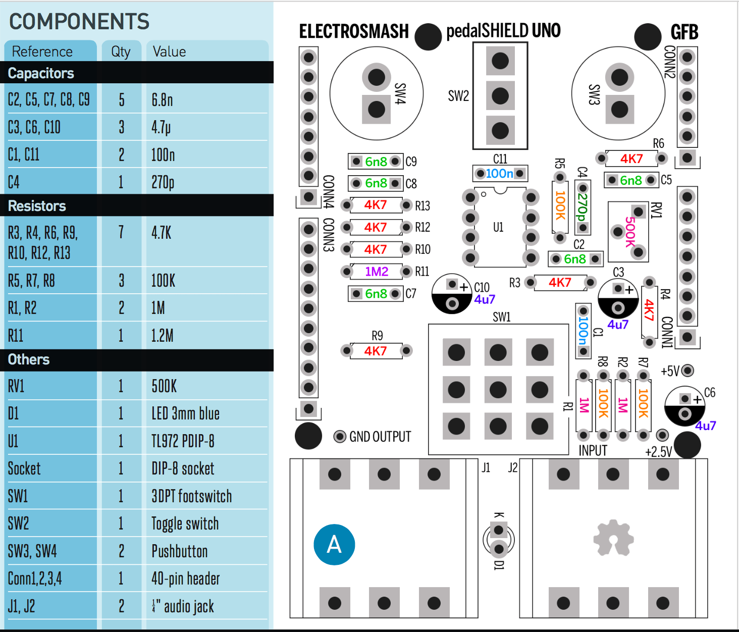
This entire project is open source and open hardware; all the schematics and files are free. The design was created using KiCAD, an open source ECAD for Win-Linux-Mac so everybody can contribute. Learn more at our website. Here’s how to build your own.

Project Steps

1. SOLDER THE RESISTORS

There are 13 resistors to be placed, shown in the PCB diagram (Figure A) and in Figure B:

  • 4.7K resistors (7 units): R3, R4, R6, R9, R10, R12, R13.
  • 100K resistors (3 units): R5, R7, R8.
  • 1M resistors (2 units): R1, R2.
  • 1.2M resistor: R11.
Figure A. Click for larger version
Figure B

In order to solder the components, bend the leads close to the body, place them through their footprint on the PCB, and solder on the back of the board. Cut the excess leads as short as possible to avoid short circuits. To learn more about how to solder, check out the below video:

YouTube player

2. PLACE THE CAPACITORS

Figure C

There are 8 film/ceramic and 3 electrolytic caps. Solder them as shown in Figures A and C:

  • 6.8nF capacitors (5 units): C2, C5, C7, C8, C9.
  • 4.7µF electrolytic capacitors (3 units): C3, C6, C10.
  • 100nF capacitors (2 units): C1, C11.
  • 270pF capacitor: C4.

Be careful with the electrolytic caps’ polarity; the negative lead (the short one) has to be placed in the round hole with the semicircular marking. The positive hole is always square-shaped.

3. ADD THE MEDIUM-SIZE COMPONENTS

Figure D

Place the DIP socket (U1), 500K trimmer (RV1), and LED (D1) as shown in Figures A and D.

Take care with the LED soldering: The short lead (cathode), on the flat side of the diode, goes into the hole marked with a “K” on the PCB.

4. SOLDER THE BIG COMPONENTS

Figure E

Place the pushbuttons (SW3, SW4), toggle switch (SW2), 3PDT footswitch (SW1), jack connectors (J1, J2), and header pins (CONN1, 2, 3, and 4), as shown in Figures A and E. Press the op-amp chip into the DIP socket, as shown in Figure F.

Figure F

When soldering the potentiometers and switches, check their positioning against the plastic cover; it will fit better if it is aligned. Be careful soldering the big components perpendicularly because they tend to be slightly tilted.

Cut the 40-pin strip into 4 segments of 6 pins, 8 pins, 8 pins, and 10 pins. You can use wire cutters, or carve a groove with a utility knife and then just bend it carefully to break it.

Because the USB connector on the Arduino is positioned too close to the output jack, isolate it with some duct tape to avoid short circuits.

5. CHECK YOUR WORK

You should now have a mounted board exactly like the one shown in Figure F. Double-check your PCB with the model, component by component.

Before powering it up:

  • Visually inspect the bottom of the PCB, ensuring there are no short circuits or long, uncut leads.
  • Check that the polarized components (the LED and electrolytic capacitors) are placed correctly.
  • Ensure that the op-amp is not upside down.

If you need more help, there’s a topic in the forum called “Guide to troubleshoot pedalSHIELD UNO.”

Figure G

Finally, the plastic cover can be placed — the footswitch’s nut and plastic washer keeps it in place, simple and neat (Figure G). Now just plug the shield into your Arduino Uno. (For performances, consider creating a fully supported enclosure to keep from damaging the electronics.)

NOW ROCK OUT


You can program your own effects in C/C++ or get inspired by our ready-to-play effects: booster, distortion, fuzz, delay, vibrato, tremolo, “Daft Punk” octaver, and more. Grab the Arduino code, plug in, and rock out!