
Some people love to launch model rockets, and personally I’ve always wanted to launch a stratospheric balloon up to “the edge of space.” We don’t exactly do the same thing for the same reasons, but there’s one thing we would all love: to have our payload come back to Earth exactly where we want. Not in the trees, not 200km away, not on a road or in a lake.

How could hobbyists, scientists, and meteorological companies simplify the recovery of their craft?
R2Home is part of the solution — a smart, GPS-guided parachute recovery system. As a generic and fully autonomous flying robot, its job is to make sure your payload comes back exactly where you want it to land. Just send it. R2Home takes care of the rest.
Precisely control the descent trajectory of your rocket or weather balloon experiments and you have more valuable data. Launch many more of them for lower cost; recovery isn’t a problem anymore and you’ve opened the way to reusability.
We can also dream bigger: Drop it around Mars and you’ve got the first robotic explorer of Mars’ upper atmosphere!
Sixty years ago humanity reached space. The next space race is about coming back to Earth in a smart, guided, and safe way.

THE CONCEPT
Let’s suppose you are the R2Home robot. The balloon above your head just exploded, or your rocket separated — uh-oh, looks like you’re in freefall! Your mission is to deploy a steerable parachute, and guide it to the desired landing point (Figure A ). Alright, OK, but how do we
get there?

HOW DOES IT WORK?
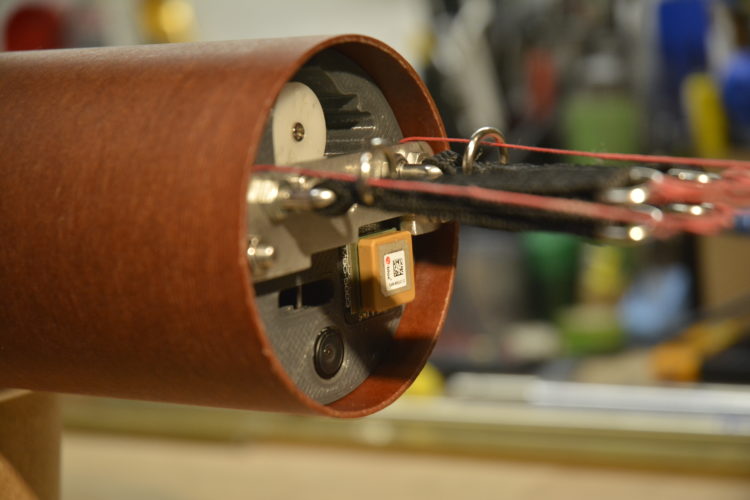
There are three main components, shown in Figure  B (from left to right): the pilot or drogue chute, the steerable wing parachute folded in its deployment bag (aka “D-bag”) and the R2Home body tube containing all the mechanics and electronics.

DEPLOYING THE WING
How do we deploy the wing, or in other words, how do we go from Figure C to Figure
  D?
D?


The wing parachute is folded in the D-bag following a precise pattern to avoid tangles during deployment. We need a way to get the wing out of the D-bag at the right time or right altitude. The drogue chute is used as an extraction force. The deployment mechanism allows us to use this force at the right time.

Before deployment, the drogue is pulling on the orange line on the D-bag (you can spot it in Figure E ), which is connected to the deployment mechanism in the body tube. As soon as the deployment is triggered, this orange line is released and the D-bag is pulled away from the body tube. The wing chute’s lines are then pulled from the bag until they are tight and the chute is pulled from the bag (Figure
  F).
F).

Thus, once the system with the drogue chute has reached its terminal velocity, i.e. about 5m/s when the drag force is equal to the weight, the force exerted by the drogue on the D-bag is almost directly the weight of the system.
The drogue chute is an interesting problem. It’s as big as possible for safety — if the wing deployment fails, R2Home is still falling slow enough to avoid destruction. However, after wing deployment, the drogue remains attached to the wing, and therefore if it’s too big, it will prevent the wing from flying properly. The solution is to use a “magic” or collapsible drogue chute, which can be both large before deployment, and small after (Figures G and H
and H ).
).


The automatic deployment of the parachute is triggered by a condition of vertical speed, deduced from the barometer, and altitude, merged between the GPS and the barometer. For example, if we want to deploy the canopy at 100 meters, we look to see if the vertical speed is lower than –3m/s and the altitude lower than 100m, and then the deployment is triggered.
FLYING AUTONOMOUSLY
Alright — so your parachute is opened, well done! Now we want to steer it autonomously to the desired landing point. The first question is how to steer the parachute?


With R2Home you can use a few different types of parachutes. Ram-air parachutes (Figure I ) or single-skin paragliders (Figure J
 ) are both good solutions; the first one is easier to deploy, the second one flies better. The good news is that we can steer both of them the same way!

We use brake lines connected to the right and left trailing edges of the wing. When the right brake line is pulled, the right side of the parachute is braked, and the parachute turns right (Figure  K). And vice versa for the left line (Figure L
 ). To turn, you have to pull one line, and release the other, in a very precise way, over a distance of about 8cm, using servomotors.

A normal servo typically has a rotation of between 90° and 180° (120° on average). However, a rotation of 120° on a small enough spool to fit in R2Home’s tube volume would move the brake line only about 2.5cm — not enough.
The solution is to use a continuous rotation servo with a feedback sensor which gives us the position over 360°. This servo has a microcontroller integrated inside (you can see its USB-C connector in Figure  M) to control the rotation speed of the servo to reach the desired position with a PID control program. It is thus possible to control this servo like a normal servomotor, but on a range of about 360°. This way, we can pull our line more than 8cm. A 3D-printed drum prevents the line from getting out of the spool (Figure
  N).
N).


Now that we can steer the wing, we have to fly it to the right landing point with an autopilot, so that everything is fully autonomous. R2Home’s onboard flight computer (Figure O ) is based on a Teensy 4.1 microcontroller. Its purpose is to manage the entire system autonomously: to deploy the wing at the right altitude, steer the wing, record all flight data at different frequencies depending on the flight mode (climb, descent, canopy flight, etc.), and send data to the ground by radio telemetry (at a lower frequency to save power). It also contains several different power supply circuits, to avoid conflicts between the motors and the control electronics.

The autopilot works as follows: We’re trying to move along a course from our current position to our landing position. To move in this direction, we want to correct our current direction, given by the GPS as “course over ground.”
Once the direction error is calculated, a command can be deduced — turn left or right —
using a PD (proportional-derivative) control program. The larger the error, the larger the command, but if the error decreases very quickly, the command is also decreased to avoid overshooting the desired direction.
Figure  P shows an example of the autopilot’s work with real flight data. The yellow curve is the desired direction, and the red curve is the measured direction. The autopilot is engaged at the very beginning of the graph. The variation around T+100s represents the moment when the system flies exactly over the desired position,
and thus the desired direction changes by 180° very quickly.

We can see that the error is corrected without oscillations, but also that the parachute’s direction has a slight delay from the command given to it. This delay is almost impossible to remove; a paraglider or parachute wing simply takes some time to turn.
The ultimate test for the autopilot is to bring the system back to a landing point from all directions (Figure Q ) and see how good it is at coming back home!

HOW TO TEST IT?
Testing the system is essential. It took me more than a year of test flights to develop R2Home. At first I attached a motor and prop to it, but the best solution I found is to drop it from a drone. We need a drone big enough to lift about 1kg, and if possible with autonomous flight capabilities. I’ve been using a secondhand DJI S800 hexacopter (Figure Y ) with an INAV flight controller, modified to remotely trigger the deployment of R2Home.

We use this drone to lift R2Home up to 100m high, and 100m away (Figure Z ). For the test to be successful, R2Home has to autonomously deploy its parachute at the right altitude, and steer it to the landing point.

Figure Aa shows the GPS traces of two flight tests on the same day, from a similar drop location. The wind was coming from the left of the image, so R2Home had to fly upwind to the landing point. The yellow line is the straight line between drop and landing, about 125m long.

For your flight tests, find the largest field you can — either public but not crowded, or private and you know the owner. If your field is too small, during your first (often failed!) tests you risk losing your system too often.
And here we go — R2Home is back home (Figure Bb ), after deploying its parachute at the right altitude and flying all by itself until reaching the desired landing point with precision!

The autopilot flies in a straight-ish (curved due to the wind) line toward the desired landing point. Once this point is reached, it will naturally rotate around it until landing is achieved.
WHAT’S NEXT?
The R2Home system is now proven to work on low-altitude flight. It took more than a year of flight tests and failures (and learning!) with several prototypes to get there. Next on the list:
• Testing from higher altitude, ~1km, using a balloon or a model rocket
• A smarter autopilot with waypoints and multiple “safe zones” where it can land
• Supporting you in building your own R2Home (Figure  Cc), to get it flying all over the world!

My ultimate goal is to continue this project up to a flight at 30km altitude, setting new records for such a tiny robot and making R2Home, with your help, a useful and much-used system to make science easier and help us explore the world! 
 , S
, S , U
, U , and T
 ) includes the Teensy flight computer, GPS module, and altitude sensor, the steering servos and a micro servo to release the D-bag, a LiPo battery, and an ultrabright RGB LED — all secured with 3D-printed parts, threaded rod, and various hardware.


 ; link in bio) and more info on
  ). The sleeve is only connected to the D-bag. As soon as the wing chute is out of the D-bag, the sleeve is free, and the drogue is closed.
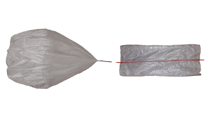
 X), but there might be other ways to do it. First, get it flat on the ground. Then pull the wing and tension all lines. Then gather it into a cylinder while making sure the tip of the wing is always either on the top or the extreme side of the cylinder. You don’t want anything (fabric or line) to be after the wingtip. Then fold the cylinder in half and compress it into the D-bag. Finally, place all lines in the spot provided for in the bag.