This project combines a number of unrelated technologies to provide a small convenience.

The essence of this project is to remotely actuate a switch connected to the garage door opener when a GPS-enabled smartphone enters a pre-defined geographical trigger zone.

In addition to the motorized garage door opener, the following components are used in the system:

  • X-10 Universal Module UM506,
  • X-10 Computer Interface CM11A,
  • Lantronix XPort Evaluation Board,
  • D-Link Ethernet Router DI-624,
  • Android-based smartphone

Project Steps

Hardware setup:

Setting up the hardware components is straightforward. To start with, my garage door opener has a connection for a manual pushbutton and thus I simply attached the relay contacts of the UM506 Universal Module in parallel with the pushbutton. Also, I configured the module for momentary closure and plugged it into a nearby AC outlet so that it can communicate with the CM11A X-10 Controller over the house wiring.

The control end of the CM11A Interface is a standard RS-232 port which is normally connected to a PC but for this project I connected it to the RS-232 side of the Lantronix XPort Evaluation board (I had to build a short gender-changer adapter cable)

The Ethernet side of the XPort connects to my home computer network which in turn is connected to the Internet via an always-on, broadband connection.

I should point out that one could also use a PC and a simple program to bridge the RS-232 connection of the CM11A Interface to the Internet. The Lantronix module, however, offers two clear advantages: lower power consumption and, more importantly, the ability to recover without intervention in case of a power outage. On the other hand, the software bridge could be designed to be highly secure.

Software configuration:

The overall software setup for this project is far from trivial mainly because of the required development of the App for the Android smartphone. However, the configuration of the hardware devices is relatively easy.

Lantronix XPort:

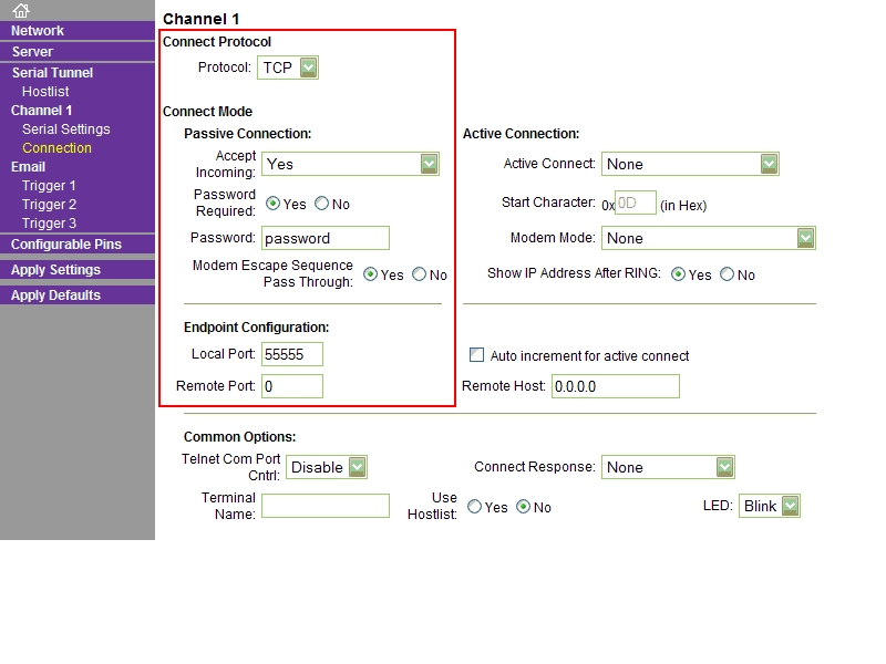
Because of the requisite port forwarding, the XPort module should be configured with a static IP address within your home network. But before you can make any configuration changes you will need to know the IP address assigned to the module when it is first attached to the network. You can go about this by using Lantronix’s Device Installer utiliy. From this utility you can also access the device’s configuration pages.

The relevant items to configure are:

Network | IP Configuration: select “Use the following IP configuration” and supply suitable values for the IP Address and Subnet Mask

Channel 1 | Serial Settings | Port Settings: the required Baud Rate for communicating with the CM11A Interface is 4800 bps. The remainder of the fields can be left at the default values.

Channel 1 | Connection: here enter a value of your choice (or use the default) for the Local Port under Endpoint Configuration. You can also provide for a little bit of security by requiring a password to complete the incoming connection from the Internet under Passive Connection.

Network router:

A port needs to be opened and forwarded to the XPort module in order to handle the control requests from the smartphone.

The procedure for this varies slightly with the router. For the DI-624 the configuration is set in the Virtual Server page of the Advanced tab.

The other configuration change required for the router stems from the fact that IP addresses assigned to home users by Internet Service Providers are usually dynamic. That means that the address that the smartphone needs to communicate with can change at any time.

Fortunately, many routers provide a feature called Dynamic DNS. When this is enabled, the router automatically reports its assigned IP address to a DNS server on the Internet which can then match the address to a fixed friendly name such as “myhome.net”. There may be several Dynamic DNS providers available. I have established a free, basic account with “www.no-ip.com” which is supported by the DI-624

On the DI-624, Dynamic DNS is configured on the DDNS page of the Tools tab.

The final piece of software is the Android App itself. The entire source code is contained in the GarageDoor.pdf file. Minimal familiarity with the Android development tools is required to build the App.

The friendly URL (as obtained from the Dynamic DNS provider) of the router as well as the forwarded port number have to entered in the source code and, if you require a password to complete the connection to the XPort, then it must also be hardcoded. Likewise, the geographical coordinates of the trigger point must be determined and entered. A working version of the App can be used to retrieve those coordinates.

Finally, the X-10 House Code / Unit Code of the UM506 module must be entered. The provided source code uses A1. The communications protocol for the CM11A Interface is also included.

Suggestions for improving the App might be to add user interface features to set some or all of the above items.

Note: it is likely that you can approach you house from two different directions in which case you may want to provide for two trigger zones (a change to the source code is required). The location and radius of the trigger zone(s) may also be dictated by the speed at which you can approach, the update rate and accuracy of the GPS receiver, and the latency in X-10 communications.