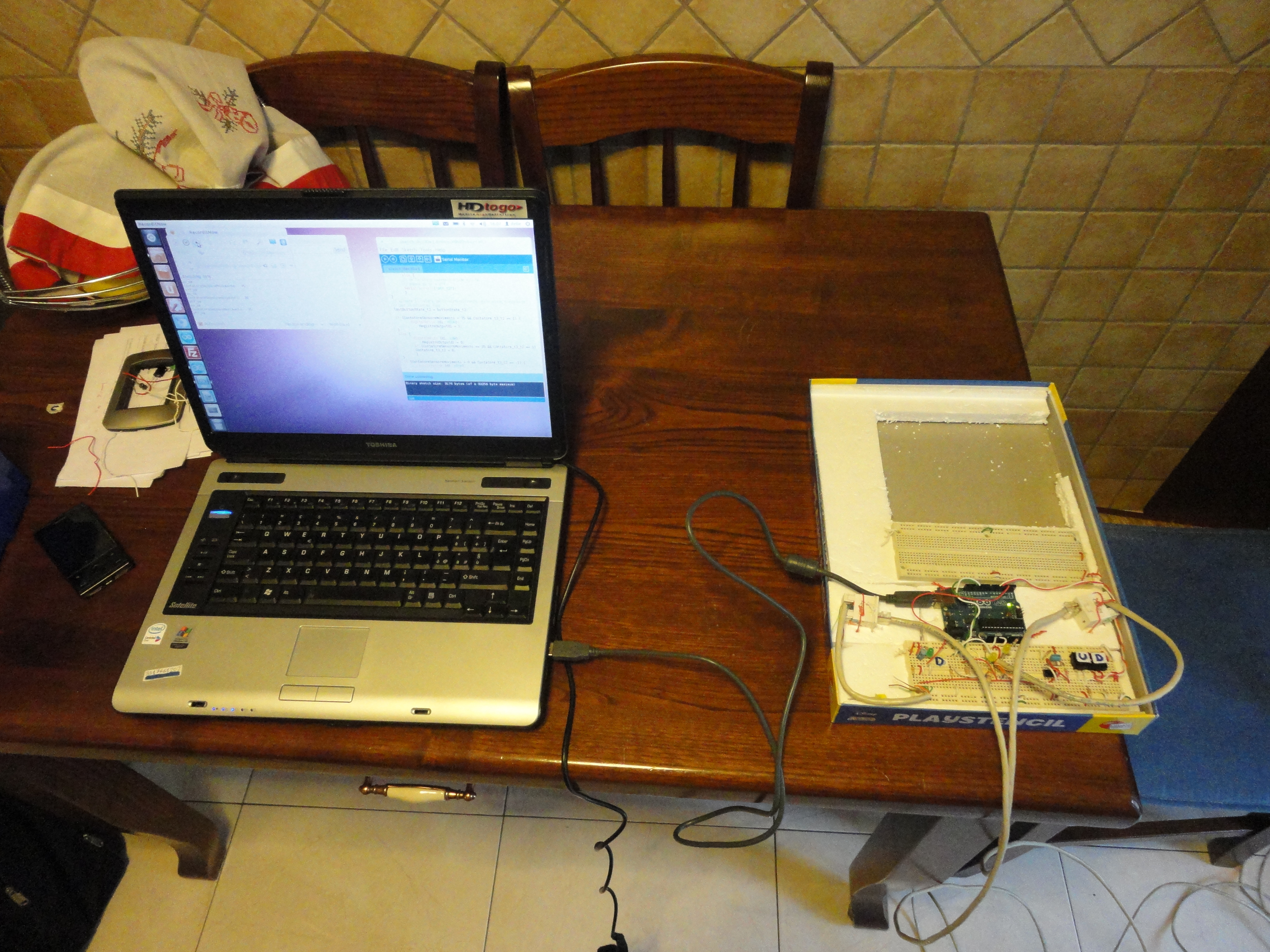
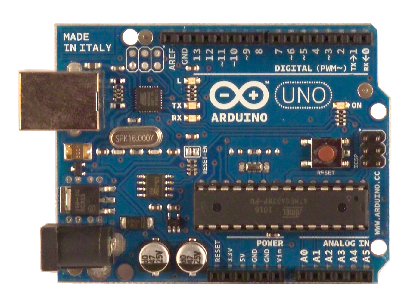
The purpose of this project is to control an electric roller shutter using an Arduino Uno. The prototype that I made is my first electronic project with an Arduino and I hope this instructable and the solutions that I found are useful for your own electronics projects. My aim was to transform an electric roller shutter into an automatic roller shutter. A possible extension of this project could be a complex automated system for a house. A central microcontroller (another Arduino, perhaps) could control all of the house’s electric roller shutters; this would enable coordinated operation at different times of day. This project is limited to a prototype; after so many years I wanted to return to building electronic circuits.
What will the next generation of Make: look like? We’re inviting you to shape the future by investing in Make:. By becoming an investor, you help decide what’s next. The future of Make: is in your hands. Learn More.

Project Steps

Functions: 1. Open and close the shutter when the appropriate button is pressed; 2. Stop the shutter when it is completely open or closed; 3. Stop the shutter when it is moving down and the “up” button is pressed; 4. Stop the shutter when it is moving up and the “down” button is pressed.

Here are some videos of the device in operation:

http://www.youtube.com/embed/DPf4oQDOABU

http://www.youtube.com/embed/ywhf1mCyTkg

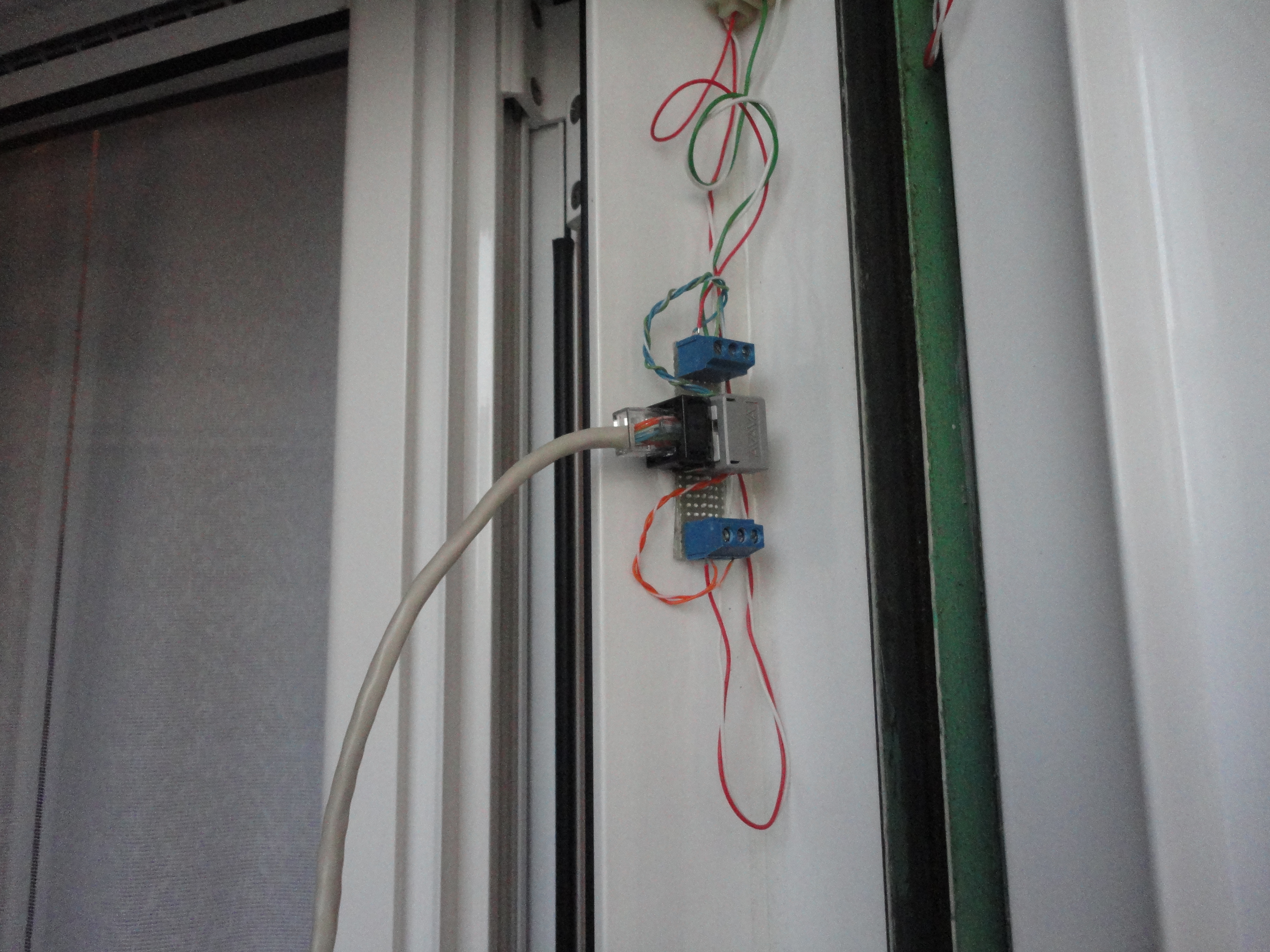
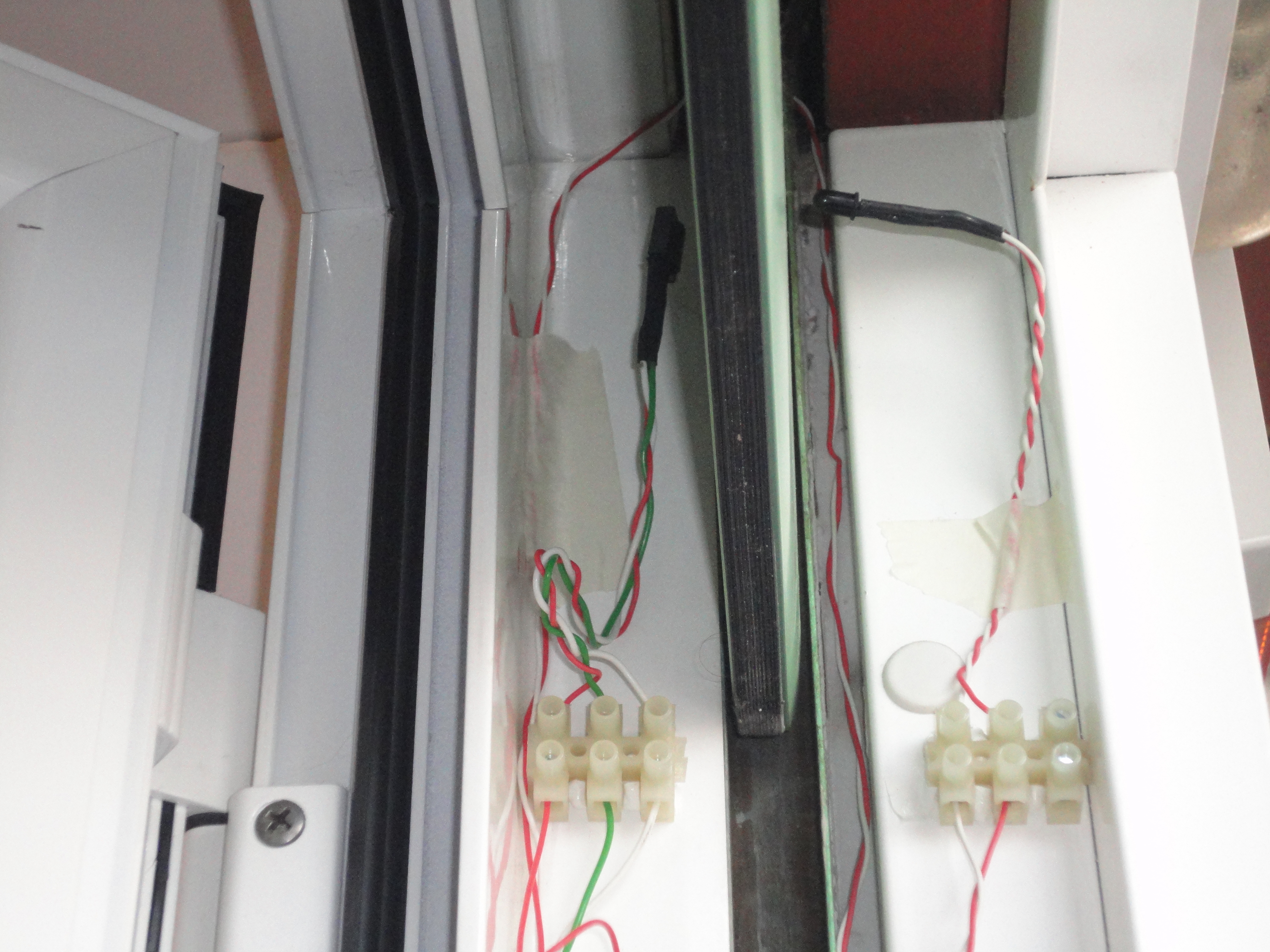
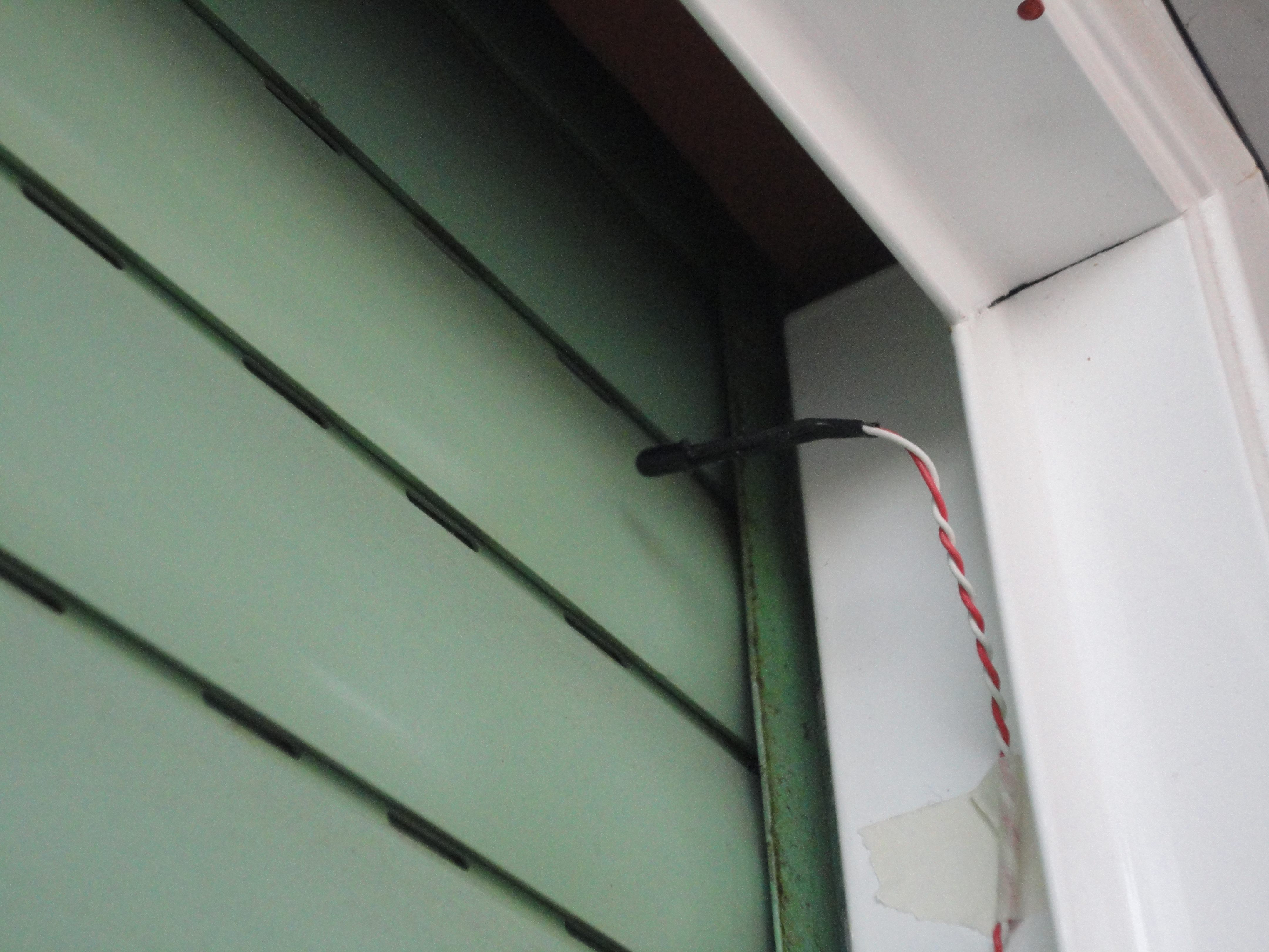
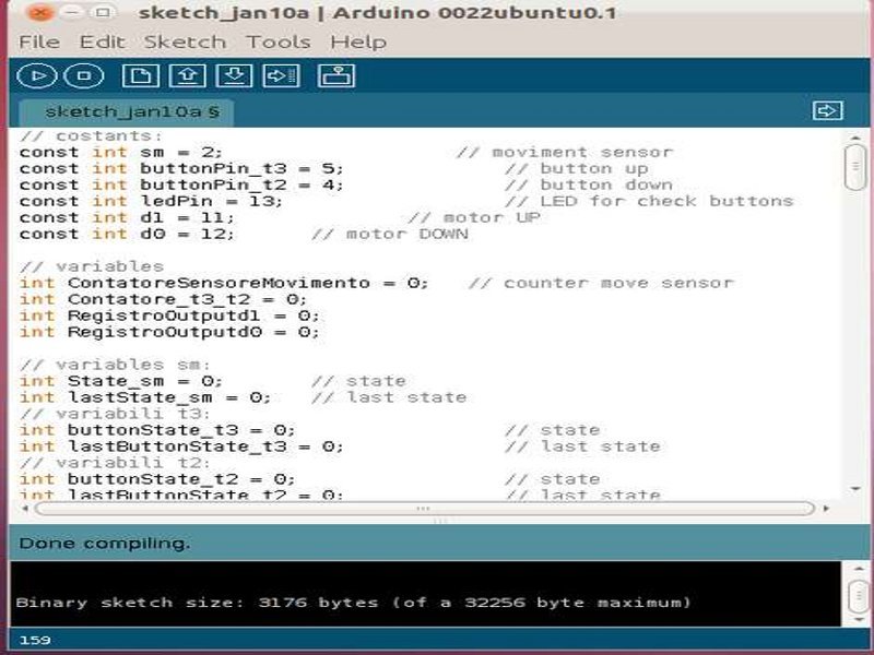
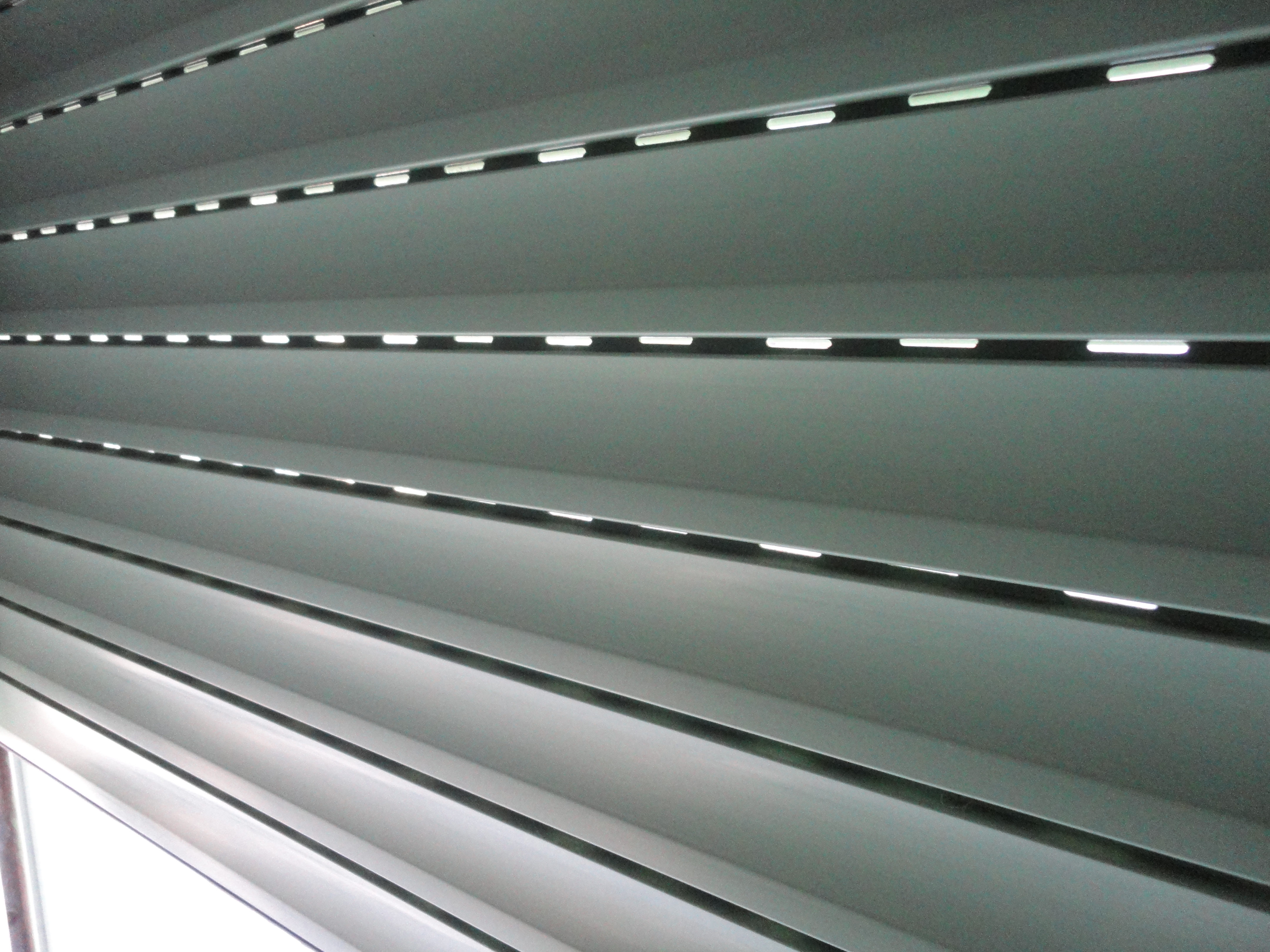
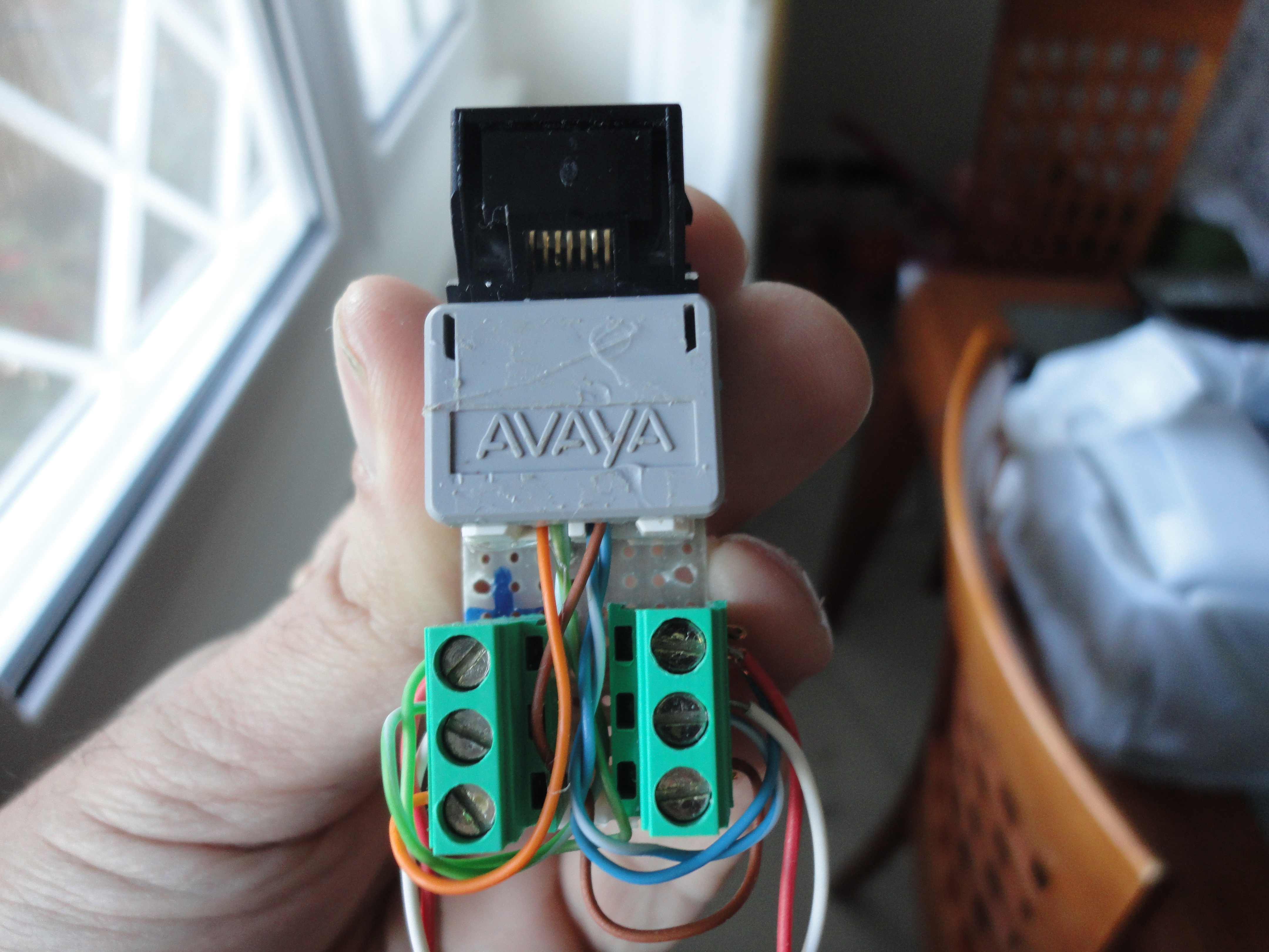
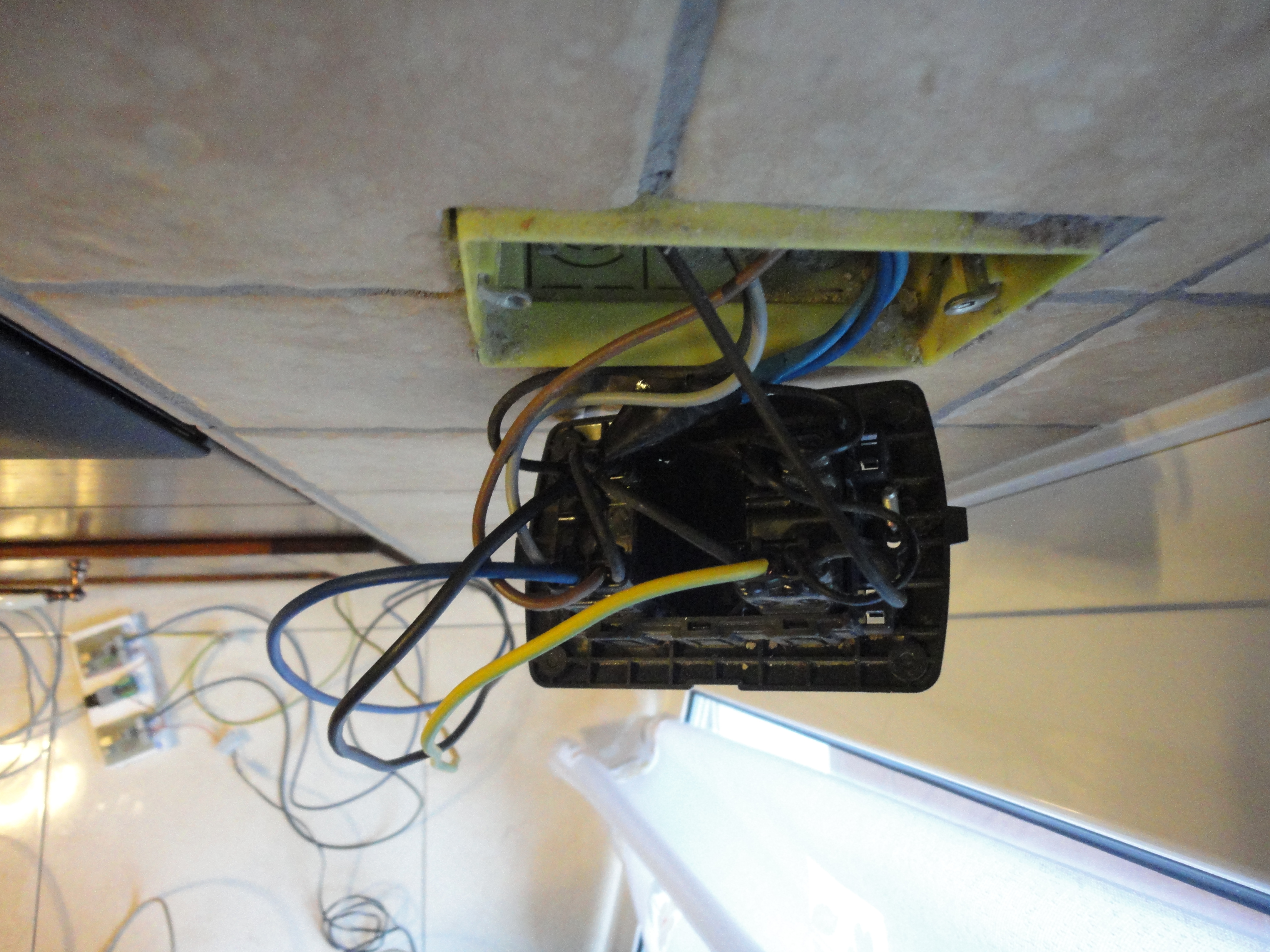
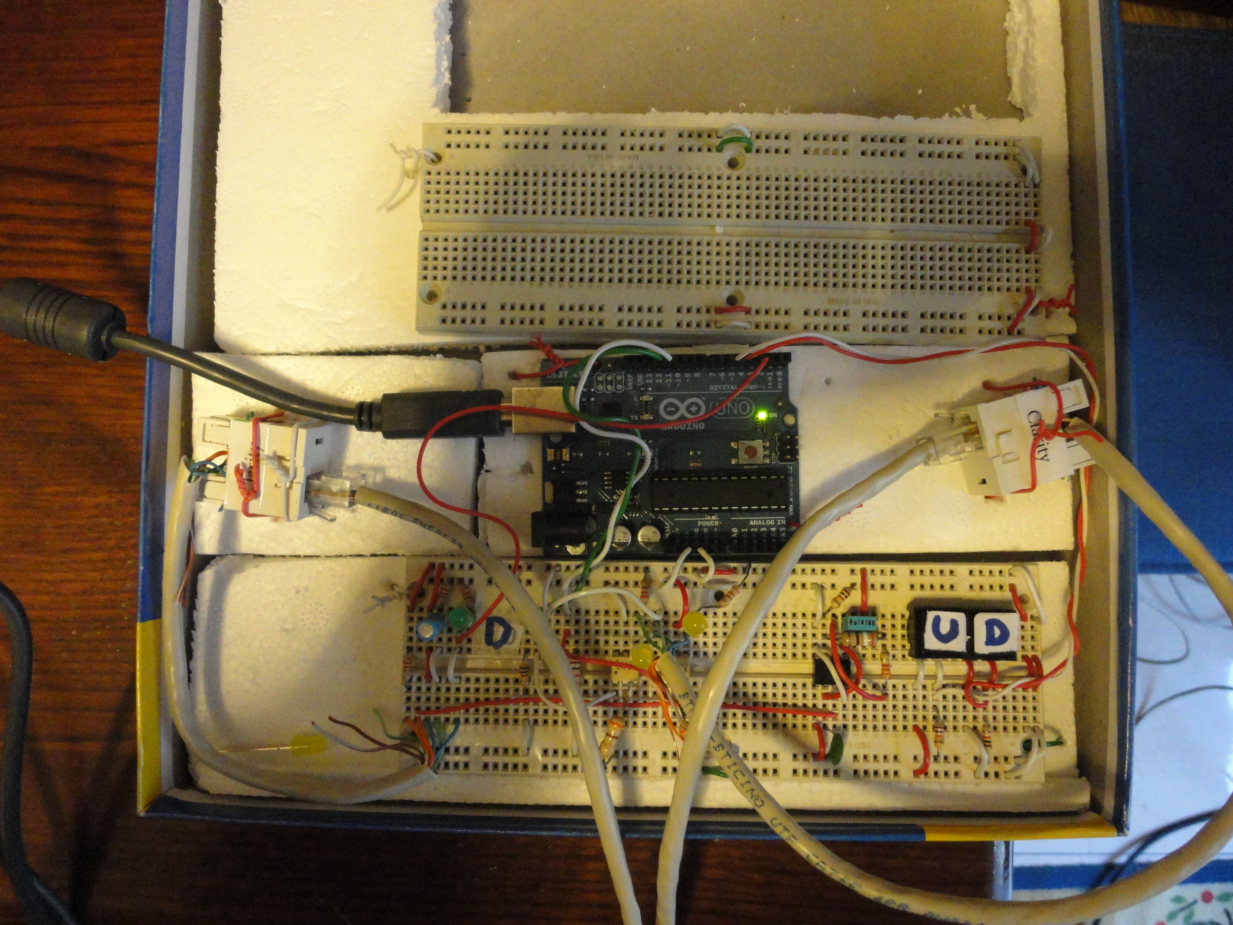
Principle of operation: The Arduino counts the holes on the roller shutter using an infrared receiver; the infrared emitter diode is positioned on the other side of the roller shutter. When a hole is sensed, the Arduino increments or decrements a counter to determine the position of the roller shutter. To connect the actuators and the sensor to the Arduino I used two LAN cables (see last step).

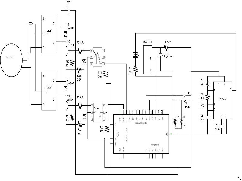
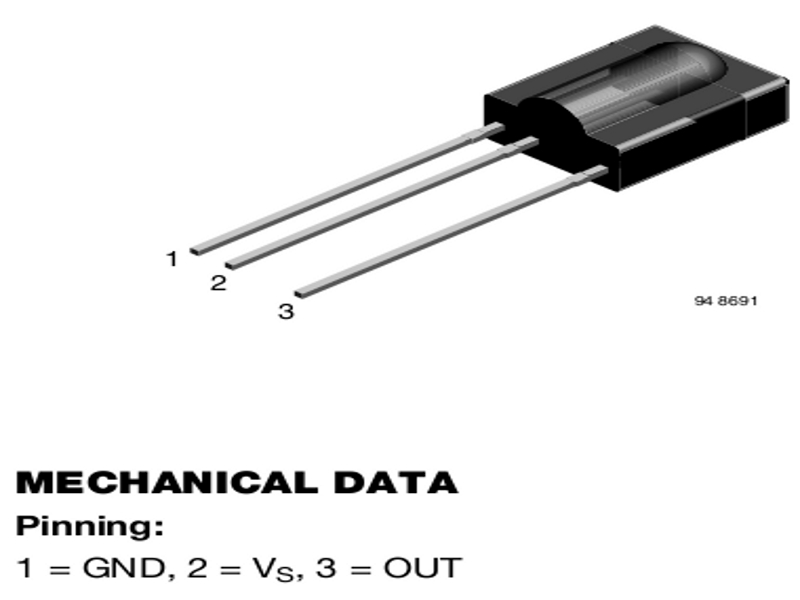
To draw the schematic I used the Dia program. It is very simple to learn, available for Linux and Windows, and it is freeware. You can download it here. The NE555 is configured as an astable multivibrator which generates a square wave at 38kHz to drive the infrared emitter. The infrared receiver is a TSOP1138 with an internal filter for 38 kHz, and the demodulated output signal can be directly connected to a microprocessor. For the safety of the Arduino I connected its outputs to two optoisolators (but this is not required).

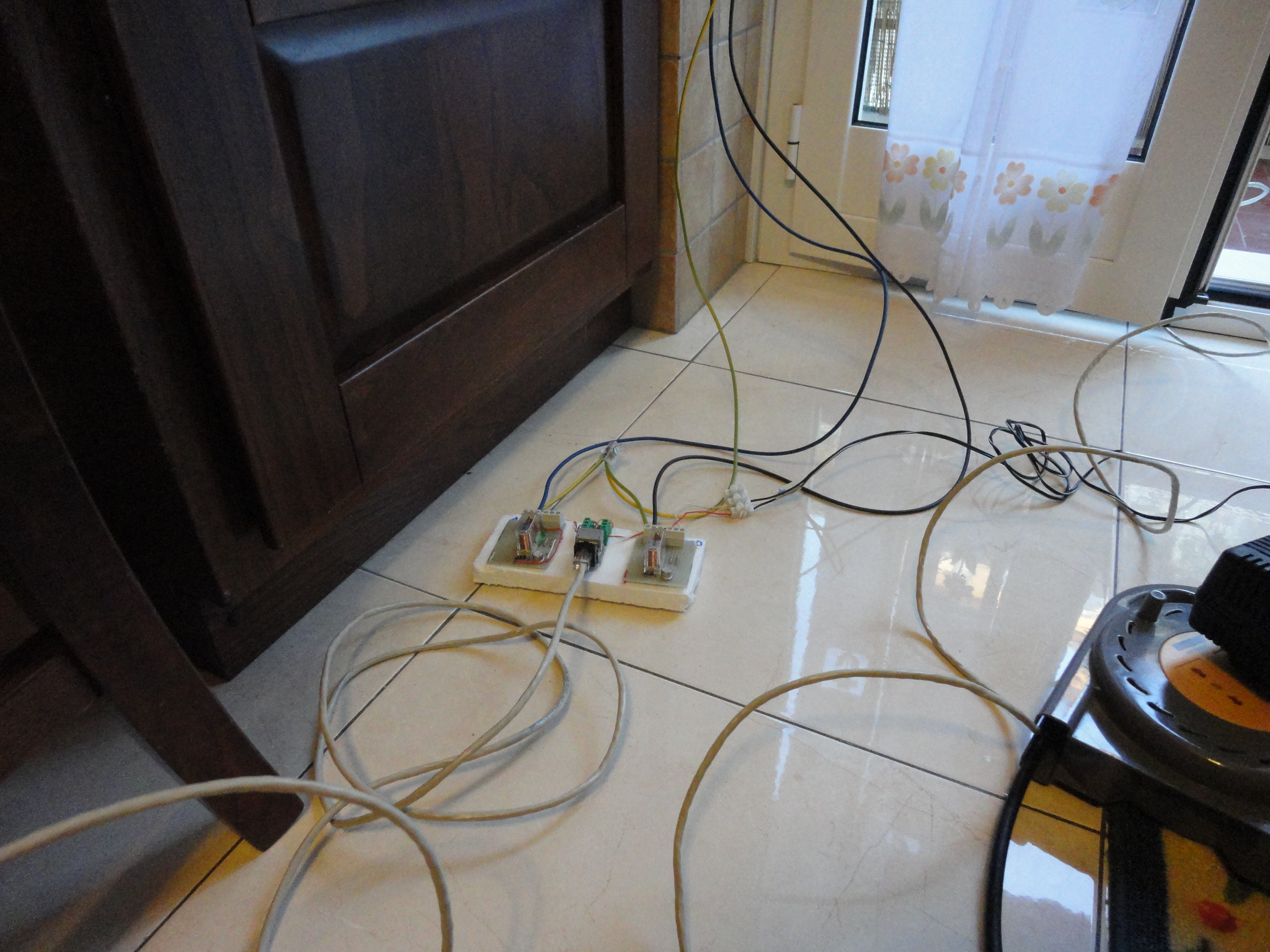
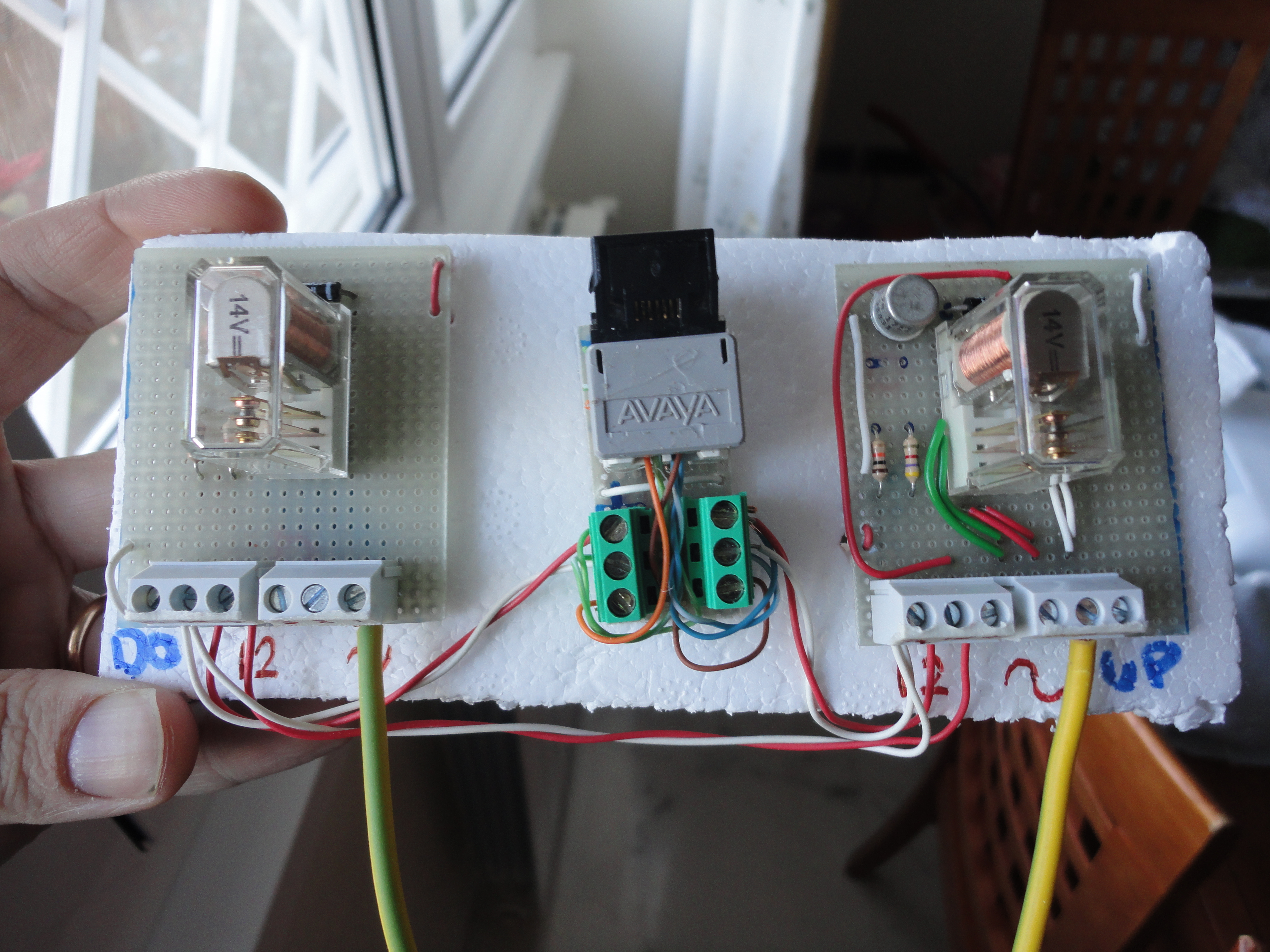
Finally, I made two actuators using two old 14v relays and a few other components such as two 2N1711 transistors, two diodes and a 12v power supply.

Here is the schematic: https://docs.google.com/open?id=0B8tHAfj…

Other photos of this project.