DobsonOpener-darkstarsky
Photos by Carrie Fay Amaro, ESA/Hubble – Akira Fujii, Hep Svadja.

Dobsonian telescopes are popular with amateur telescope makers for their ease of design and construction, portability, and their use of large optical mirrors. Pioneered by John Dobson in the 1960s, the instrument combines a Newtonian reflector telescope with a unique two-axis movable base. It uses a primary mirror to capture and reflect light, a secondary mirror to direct light into an eyepiece, and a focuser to make fine adjustments for viewing. The telescope’s size is classified by the size of its mirror.

Dobson Telescope
My finished 16-inch Dobson telescope. Photo by Carrie Fay Amaro.

I was inspired to build telescopes during a trip out to McDonald Observatory in west Texas, where I saw a 36” fork-mounted telescope, tiny in comparison to the huge research telescopes at the site.  After picking up a copy of The Dobsonian Telescope by David Kriege, I built my first telescope with a 12½”-diameter mirror, then later tackled a 12″ lightweight scope.

3 Dobsonian telescopes
Here you can see all three of the Dobsonian telescopes I’ve constructed, with the most recent on the left.

Once I’d built a CNC router, I embarked on my third telescope, featuring a 16″ primary mirror with aluminum trusses, wide vertical bearing arcs, a steel front-adjustable mirror cell, and a rotating base. The project took several months off and on to complete, although a skilled Maker could put a similar one together in a few weeks. I’m quite happy with the result, and the view in its large mirror is phenomenal.

dobsoniananatomy

All Dobsonian telescope projects are unique builds — here are the notes from my latest version to help get you familiar with the process and determine how you’ll design yours. I also have an extended photographic build diary of this telescope posted on Imgur.

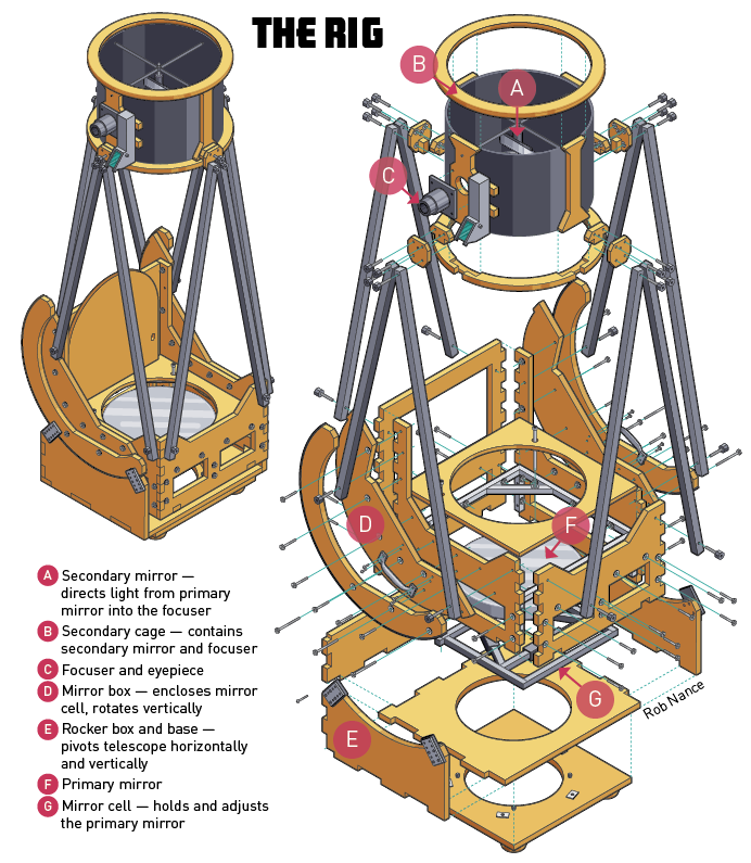
Above you’ll find an interactive 3D rendering of the Sketchup file I used to design and cut all of the parts for my telescope. You can view and download the full file here.

Project Steps

1. Construct the mirror cell

01_Mirror Cell

The core of the telescope, the steel mirror cell holds and adjusts the heavy, curved primary mirror. I welded mine from ¾” steel square tubing.

Mirror Cell Bottom View
A view of the bottom of the mirror cell with the primary mirror in place.

Because mirror flexure can distort an image, supporting the mirror properly involves building a “flotation” cell. The back of the mirror “floats” on 3 or more support points (this build uses 6) that are calculated using a software tool called PLOP. Given any mirror measurements, PLOP will provide the ideal support layout and how much distortion to expect for any number of flotation points.

Mirror Cell Measurements
A schematic reference for the mirror cell design.

As the telescope tilts toward the horizon, the mirror must be supported on its edge. Use the external Mirror Edge Support Calculator to decide whether to use a two-point, four-point (“whiffletree”), or sling support. While a sling or whiffletree provide the best edge support, a two-point edge support is much easier to construct.

Sling Style Mirror Cell
An example of a “sling” style mirror cell design.

The mirror itself must also be able to tilt in three dimensions in order to aim its light at the secondary mirror (a process called “collimation”). To do this, the mirror cell needs to be supported by 3 large bolts, at least 2 of which are adjustable. By adjusting the bolts, the mirror can be pointed toward the correct spot.

Mirror Cell Edge Close Up
A closeup look at the edge support system for the “whiffletree” style mirror cell.

2. Build the secondary cage

02_Secondary CageThis is the upper tube that contains the flat secondary mirror, Telrad finder, and focuser. In my build, the cage was cut on a CNC router from ¾” plywood, with threaded T-nuts added to support a truss assembly.

Spider and Mirror
The spider and secondary mirror mounted within the secondary cage.

The cage should be a hollow cylinder about ½” wider than the mirror, with the focuser mounted directly facing the secondary mirror. The “spider,” or secondary mirror holder, will suspend the mirror in the optical path in order to direct light into the focuser. Thin 1/16″ Kydex plastic should be cut to length to line the inside of the cage as a “baffle” to block outside light.

Closeup on Bolts
A closeup look at the bolts and threaded plates for attaching the secondary cage to the trusses.

3. Measure the cell-to-cage separation

03_Measure

Every primary telescope mirror has a fixed focal length that’s usually 4 to 6 times the width of the mirror. When you add the minimum distance from the eyepiece to the secondary mirror together with the distance from the secondary mirror to the primary, the total length should be the primary mirror’s focal length.

Focal length jig
My CAD sketch for the focal length jig.

In my build, the minimum eyepiece-to-secondary mirror distance (13½”) plus the primary-to-secondary mirror distance (57½”) equals the focal length of 71″, which is roughly 4.5 times the width of the 16″ mirror.

In order to check your measurements, you can construct jigs for your mirror cell and secondary cage, positioning them on a straight, adjustable track such as 2 planks of wood. Orient this assembly to allow you to view an object on the far horizon. Move the jigs until you can comfortably place a variety of eyepieces in the focuser and get a sharp image, then carefully measure the separation distances.

4. Design the mirror box

04_Mirror Box

The mirror box encloses the mirror cell and allows the entire telescope to rotate vertically. I built mine entirely from CNC-cut ¾” plywood, and fastened it together with 2½” bolts. It features 2 semicircular arms, and mounting points for the trusses (T-nuts are fine), as well as a lid to keep the mirror safe when the telescope is not in use.

Dry fit of mirror box panels
A dry fit of the mirror box panels after being cut on my CNC.

Building the mirror box is tricky, because the entire optical assembly (mirror cell, mirror box, trusses, secondary cage) must balance at the center of rotation of the arms. If the telescope rotates forward or backward on its own, then the mirror box is too deep or too shallow. Plan ahead by carefully weighing all components and approximating the center mass of the optical assembly.

Once built, line the undersides of the arms with textured ABS plastic as a bearing surface. Staples or finishing nails work fine, but be sure they don’t bump up above the surface of the plastic. The plastic will ride on teflon pads, creating just enough traction for the telescope to avoid sliding on its own while not making it too difficult to point at things in the sky.

5. Cut the trusses

05_Trusses

Thin-wall aluminum tubing is used to attach the mirror box to the secondary cage. While round tubing is sturdy, square tubing is easier to work with. Once it’s cut to length, drill a hole through each end of the tubing with a drill press. During on-site assembly, attach each truss to its mounting T-nut using a bolt with a thumbscrew knob.

Attachment blocks
An inside view of one of the four attachment blocks used to attach the trusses and the secondary cage.

Using plywood, make 4 attachment blocks to pair the trusses together and create a small ledge for the secondary cage to rest on while you secure it. During assembly, you’ll attach the trusses to the mirror box, then sit the secondary cage on top and bolt everything in place.

6. Build the rocker box and base

06_NEW_Rocker Box

Made of ¾” plywood, the rocker box supports the mirror box on 1″ teflon pads, allowing it to rotate vertically. The rocker arms must also have guides to keep it on the track; flat metal 1½”×2½” braces lined with ABS plastic work nicely. The box should be deep enough to allow the mirror box to swing all the way down. Line the underside of the rocker box with a ring of ABS plastic to allow it to ride on the base.

Rotating base
White PTFE bearing pads on the lower base match up to the ABS plastic ring on the upper half.

The base of the telescope should be a wide, sturdy square or circle of wood with teflon bearing pads matched to the ABS plastic ring of the rocker box. And the legs of the base should be as wide as possible to accommodate weight imbalance as the telescope is moved around, to avoid tipping. The base and the rocker box in my telescope are secured with a skate bearing assembly but could be more simply attached with a bolt through the center.

7. Finish with a light-blocking shroud

07_Shroud_CFL
Photo by Carrie Fay Amaro.

Once your telescope is assembled, drape black woven velveteen around the truss assembly, clipping it with safety pins. Make sure the shroud can slip on and off of the assembled scope, and that it stretches along the circumference (not lengthwise). Sew the seam, and sew an elastic cord into the top to secure it to the secondary cage. Trim off any unused fabric along the base.


•••
 

Night view
Photo by Carrie Fay Amaro.

Dobsonians come in all shapes and sizes, from small 4″-8″ builds all the way up to massive 24″-36″ creations. Because the basic movement and optics requirements are relatively simple, much of the design is left to the builder. Be creative! And, once your telescope is finished, be sure to join a local astronomy club to learn more about the sky and share your hobby with others.