This article appeared in Make: Vol. 92. Subscribe for more maker projects and articles!

The smartphone is our favorite tool, but also a huge time waster. If you need a little help with self-control, grab a 3D printer, some electronics, and these instructions. This tiny time-controlled safe makes your smartphone disappear for a while and frees up time for other things.

First, something important up front: we’re printing our safe in plastic, so it’s not theft-proof and does not offer a 100% guarantee against misuse. If you lock up your children’s cellphones, you have to expect that their intrinsic motivation will be so high that they’ll find ways and means to break in, either by programming it or by using brute force. The point of this project is to show you how to build a device like this, what you need to think about, and to give you tips and tricks for further expansion. 

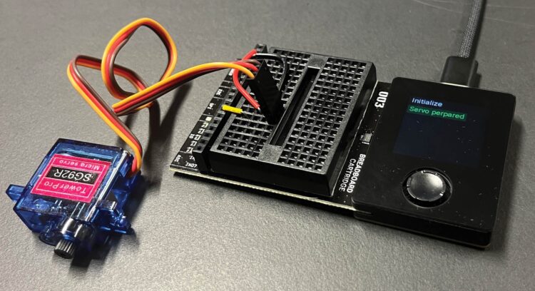
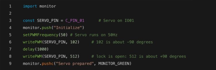
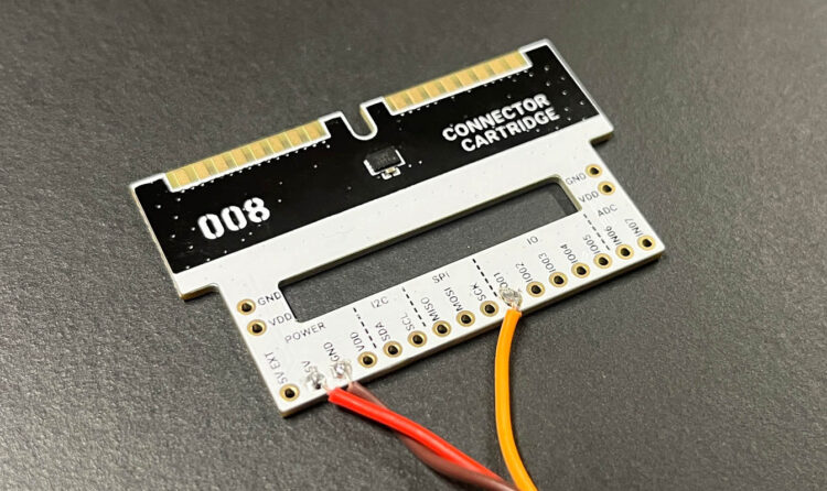
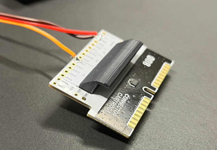
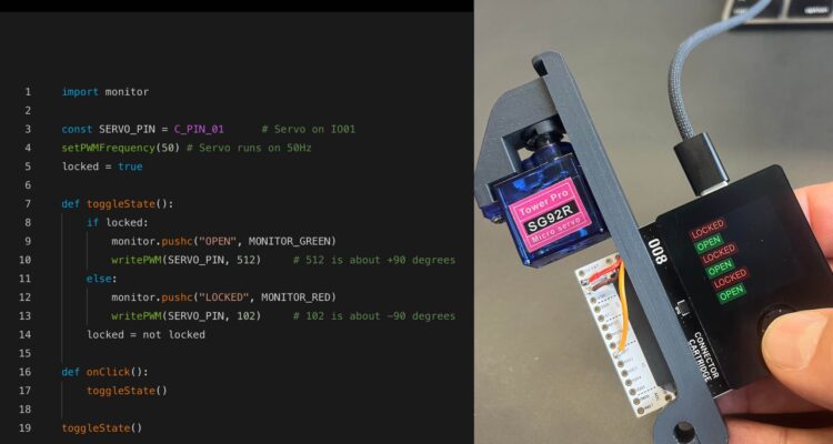
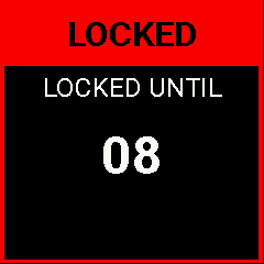
Our cellphone safe — you could also call it a prison — consists of a container and a lid. The lid contains a locking mechanism that is controlled by a servo. The device is plugged into an external microcontroller ­via a connector cartridge. We use the Oxocard Connect here to make things easy. This runs a small app that allows you to set how long the safe should lock the phone away. As soon as the time has elapsed, the safe opens and you can check your emails again or swipe and scroll through the endless expanses of social media to find the latest “news.” 

Mechanical structure

Mechanics and electronics are hidden in the removable lid.

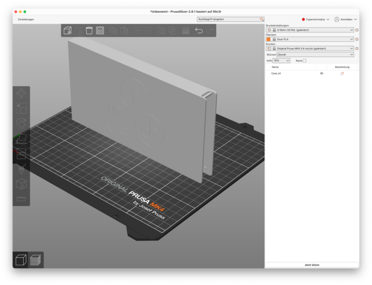
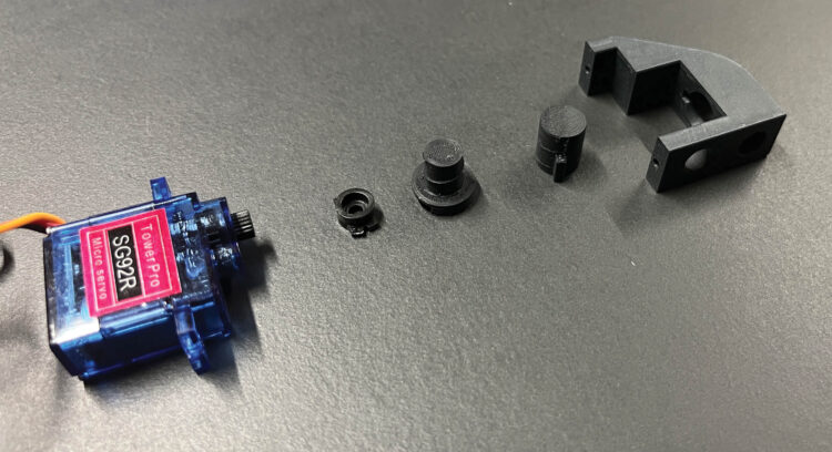
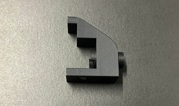
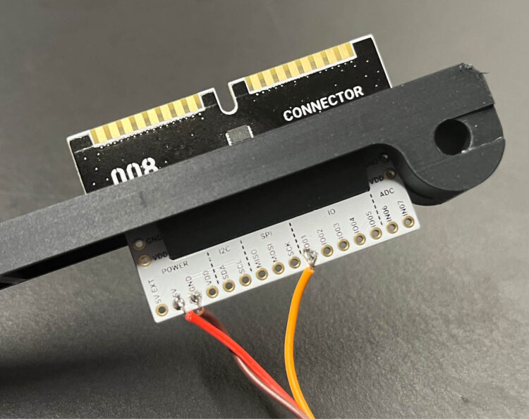
The appliance essentially consists of two parts, the container and the lid with the locking mechanism. The lid is simply inserted by opening it fully (90°) and placing it over the two short axle cylinders. A crossbar fits on the other side so that the lid can be locked in place. When the servo extends the bolt, the housing is closed.

Closing mechanism

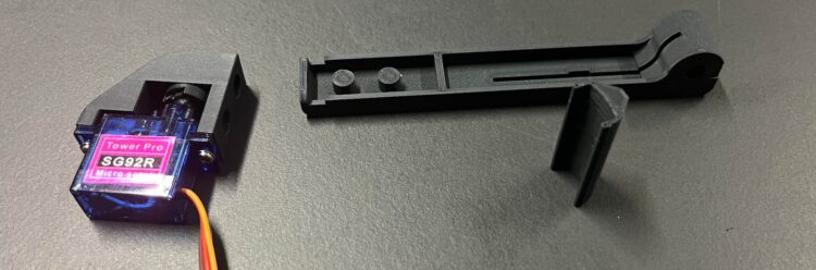
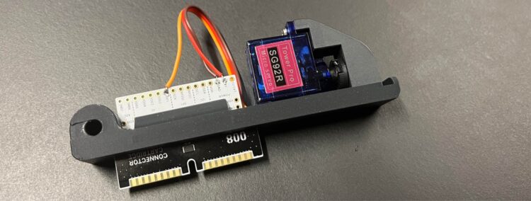
The core of this safe is the locking mechanism. For this we use a commercially available micro servo (SG92R) as found in the Make: Oxocard Connect Innovator Kit.

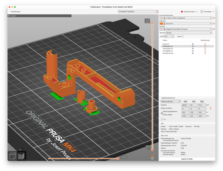
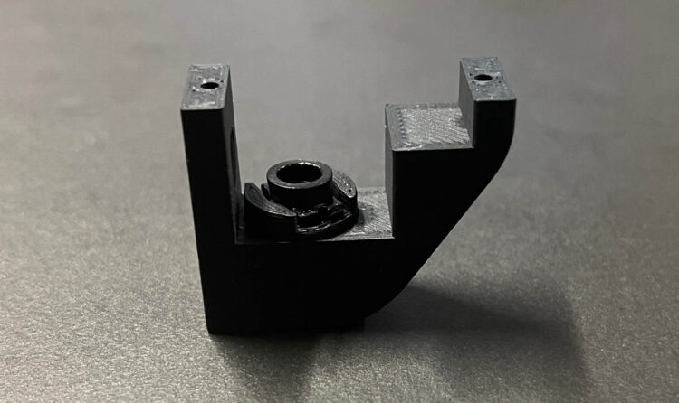
The servo is mounted in the lid and controls a closing mechanism that converts the servo rotation into a linear lifting movement to move a bolt. For this we need a servo with a truncated servo horn. Onto this, we place two plastic parts that screw into each other, to create the screwing movement. The outer part is prevented from rotating by two small rails, so the bolt moves outward and the rotary movement is converted into a lifting movement.

To move the bolt, the rotation of the servo is converted into a linear stroke using a screw mechanism.

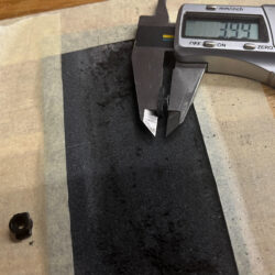
The whole thing is reminiscent of a screw with a nut. If we turn the screw while holding the nut with our fingers, we turn the screw in or out. But because the servo rotation is a maximum of 180°, we need a much higher thread pitch than a screw. In our case, the thread pitch is approximately 4mm–5mm. At 180° rotation, the stroke distance is approximately 2mm–2.5mm.

What will the next generation of Make: look like? We’re inviting you to shape the future by investing in Make:. By becoming an investor, you help decide what’s next. The future of Make: is in your hands. Learn More.

Project Steps

Preparation: printing, cutting, and some sanding

The Oxocard Connect Innovator Kit and a Connector Cartridge are required to replicate this build. All other parts are 3D printed. We also need some plastic glue in a few places to hold the parts in place.

I recommend PLA as the material. I made the parts with matte black filament from the manufacturer ESun. The container is printed with white PLA from Prusa.

The housing can be printed with 0.1mm or even 0.2mm layers, and does not require any support material.

For the large container, a layer height of 0.2mm is sufficient and you can print at speed; I have achieved the best print times and quality with a vertical transverse alignment, without support.

When printing the remaining parts, the alignment on the printing plate is crucial. The thread must be printed in such a way that no support material is required. The parts are printed with a layer height of 0.1mm in slow mode.

The arrangement of these internal parts is important, so you don’t have any support material in critical areas.

It’s important to assemble and test the parts after printing, before we insert the servo. The ServoScrew and ThreadBolt must be able to be screwed together without resistance. Sometimes there is still some material that needs to be removed by hand. Screw the parts in and out a few times until everything runs smoothly. Then the ThreadBolt goes into the housing (LockCase2). Here, too, push the bolt in and out a few times until it moves without resistance.

Various servo horns are included with the servo. We’ll adapt one of these for power transmission. Trim off the arm(s) so the total length does not exceed 11mm. Then sand down the thickness on the top side to 4mm–4.2mm using 400-grit sandpaper.

Set up the servo

The servo is our central element. Before we put everything together, we need to make sure that our servo is set to the correct angle. To do this, we build a simple circuit using the Breadboard Cartridge included in the Innovator Kit.

Connect the servo to a pin header on the breadboard as shown, and the wires as follows:

    • Servo brown = GND

    • Servo red = 5V

    • Servo yellow = IO 01

Open up the NanoPy Editor in a browser. Then connect the Oxocard Connect and start the InstallServo program (under Examples → Publications → Smartphone Safe). The servomotor should move briefly. If not, check the cables and start the program again.

In order to operate a servo, a PWM (pulse width modulation) signal must be generated. In simple terms, this switches the current on and off in very short periods. Depending on the length (aka width) of each pulse, the servo converts this signal into an angular movement. Our servo has a range of motion of approximately 180° and is connected to pin 1. In line 5 we set the frequency to 50Hz (one pulse every 20ms). Then we can position the servo on lines 6 and 8 with writePWM (lines 6 and 8).

This script sets the servo to the correct position in preparation for assembly.

The function monitor.push() on lines 4 and 9 writes a small confirmation text to the monitor. Further information can be found in the documentation.

Assemble the lock mechanism

For this step we need the servo, the prepared servo horn, and the printed parts ServoScrew, ThreadBolt, and LockCase2.

Thread ServoScrew and ThreadBolt pieces together and insert both into the housing. If you turn ServoScrew, the bolt should be visible.

Now carefully test-fit the screw and bolt by inserting them into LockCase2. You may need to sand the parts to fit. It is important that the bolt can be pushed through the housing without force. It is also important that the screw mechanism turns without force. If everything works correctly, screw the ServoScrew and ThreadBolt together and insert them into the housing. Then insert the servo horn  and screw the servo in place with its mounting screws. Done!

Place the servo horn on top as shown here, then screw on the servo.

Next, solder the cable to the Connector Cartridge. If you’re brave you can shorten the servo cable to 50mm for a very tight fit — or you can leave a little more cable. When soldering, first tin the wires and then the pins. The circuit connections are the same as on the breadboard: red to 5V, brown to GND, and yellow to IO pin 01.

Shorten and solder the servo cable. Or keep it longer if you want to use the servo later in another project.

Next, insert the PCBHolder part (shown standing up in the photo)

into the slot of the cartridge,

and then carefully insert the PCB into the lid.

Make sure that the PCB is inserted in such a way that the EEPROM chip is pushed through the small recess. The PCBHolder is a clip that locks it in place. To make it hold even better, we recommend using some super glue.

Insert the PCBHolder clip into the slot in the Connector Cartridge board, then secure the whole thing in the lid.

Now we come to the final step: the servo with the housing is also attached to the cover with a few drops of glue. The positioning is simple, as only the two large cylinders are inserted into each other.

Software

Now that our cover is finished and all the mechanical work is complete, the next step is testing and programming.

First, plug the Oxocard Connect into a computer and transfer the LockUnlock script. A message appears on the screen and in the NanoPy editor. Our first script opens and closes the lid at the touch of a button.

LockUnlock: A press of the button closes and opens the lock.

The global variable locked (line 5) saves the current status of the lock.

With the toggleState function (lines 7–14), we set the servo angle depending on its value. In line 14, we reset the locked variable by inverting the current value: true becomes false or vice versa.

onClick on line 16 is an event procedure. It is called by the operating system when a button is clicked. Here we now call toggleState. We set the value on line 19 for the first time and thus update the screen when the script is started.

The script can be started normally via Run. One problem is that we always see the automatically started demo program of the Connector Cartridge when we plug that cartridge in. However, you can simply overwrite this by selecting our example LockUnlock and clicking on “Load onto cartridge” in the context menu. A display appears on the Oxocard, and after a few seconds, the script is transferred. Unplug and plug it in again. Now we have a first usable version of our cellphone lock, with the Oxocard serving as the key!

Timer with EEPROM memory

With your Oxocard, you can now press a button to close and open the lock. However, we want to make a time-controlled safe that is also — at least minimally — protected against misuse.

Our timer allows the user to set a number of seconds with the joystick and then lock the box at the touch of a button. After the time has elapsed, the cellphone is released again.

To implement this, we need a variable for the number of seconds, and a loop that counts down to zero. Simply done. However, the problem is that it is also very easy to manipulate the device in this way. As soon as you unplug the Oxocard and plug it back in, the variable is empty again, i.e. the time has elapsed immediately and the safe opens. We therefore have to find some way of remembering these remaining seconds between resets. If the script is terminated and restarted, we then need to load the previous value from somewhere. If the value is not yet zero, the system continues counting and only then opens.

Fortunately, each Oxocard cartridge has an EEPROM memory of 64kB. The signature of the cartridge is stored in this memory. When it connects to an Oxocard, this signature is read and a message appears in the editor indicating what has been recognized. We also overwrote the autostart script in the EEPROM earlier with the “Load onto cartridge” function. This memory can also be accessed directly via script and I²C.

We use the functions writeI2CInt and readI2CInt for this purpose. I²C is a very common communication protocol, which was invented by Philips. The address of the chip is 80. Now we need a memory address. The memory of the cartridge already contains various data. The header signature is stored in the first 256 bytes. This is followed by up to three files that can be saved. I have decided to start in the middle, i.e. at 32768, so that nothing is overwritten.

Let’s call our variable lockDurationSecs, and save the content in the EEPROM like so:

writeI2CInt(80, 32768, lockDurationSecs)

and load again:

lockDurationSecs= readI2CInt(80, 32768)

The Tresor app

Now we have all the essential parts together. We can control the mechanics, and we also know how to permanently store the data in the safe’s EEPROM. Our app now needs a small GUI to display the two states “open” and “locked”.

In open mode, the display appears green. You can now use the joystick to set the duration and press the button to lock the lock.

When locked, the display appears in red. The remaining time is counted down. As soon as we reach zero, the lock opens.

Comments on the code:

In the first 40 lines, we draw the images for the navigation aids. Alternatively, you can also click them together in the constant editor (on the right) with the pixel editor.

The script contains ten short functions, which we will briefly explain:

  • unlockServo” / “lockServo” closes/opens the safe.
  • writeSecs” / “writeLockMode” saves the current status in the EEPROM
  • readEEPROM” reads all data again
  • init” initializes the vault and sets default values
  • secsToString” converts the second into the form “mm:ss”.
  • displaySetting” draws the screen in edit mode
  • displayCountDown” draws the screen when this is closed.
  • drawBorder” draws a green or red border depending on the state
  • onDraw” is the event function that is called approx. 30 times per second and controls the actual program logic.

As soon as the program starts, all functions are loaded. Lines 186–188 are then executed. The EEPROM content is read and then a decision is made as to whether we need to carry out an initialization. Then the Oxocard calls “onDraw” and everything takes its course.

Conclusion

Enjoy screen-free time

There you have it. It only takes a few parts and, thanks to the 3D printer, no extensive tools to build a functioning smartphone safe in a short time. We look forward to your further developments and comments. Let us know your ideas via the #oxocard channel on the Make: Discord Server!

Photos by Thomas Garaio

This article appeared in Make: Vol. 92. Subscribe for more maker projects and articles!