The TurtleBot mobile robot is designed for both academic and hobbyist researchers. The open source hardware design provides excellent documentation for adding modifications and extending the capabilities of the robot in hardware or software. The robot is available for purchase as a kit or, if your research budget is limited, this guide will help you extend your TurtleBot by adding an arm.
Projects from Make: Magazine
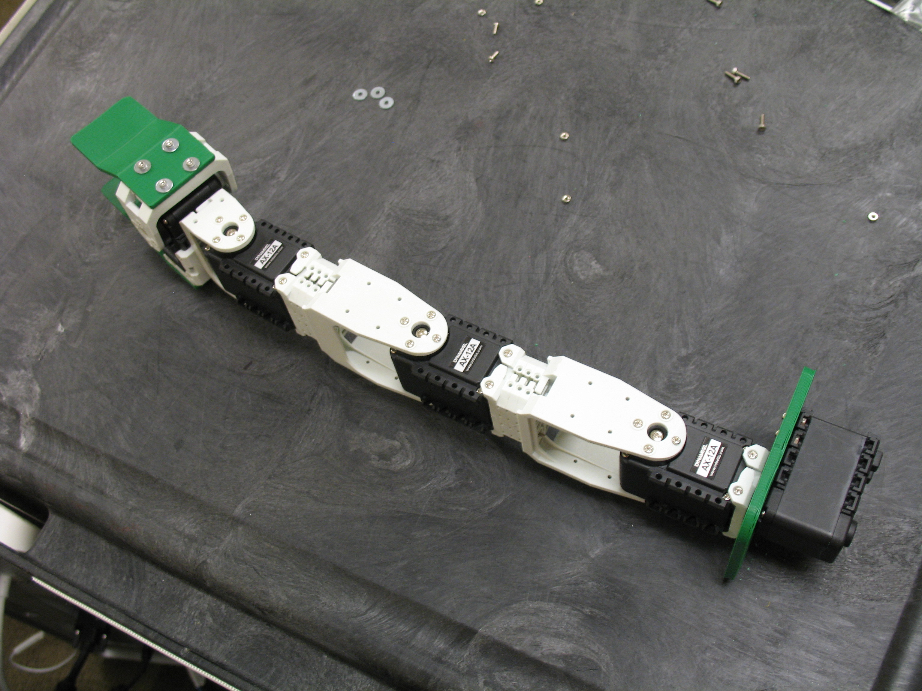
Build an Arm for Your TurtleBot
This tutorial takes you step by step through building an arm for your TurtleBot.