The Doodle Bot is a simple robot kit for beginners that can draw pictures and write text messages with a pen.

YouTube player

Sample code allows the robot to write messages created by the user. The size of the writing can be changed.

The Robot is programmed using the Arduino IDE and a USB cable. 4x AAA batteries are required.

What will the next generation of Make: look like? We’re inviting you to shape the future by investing in Make:. By becoming an investor, you help decide what’s next. The future of Make: is in your hands. Learn More.

Project Steps

Familiarize yourself with the kit before you start

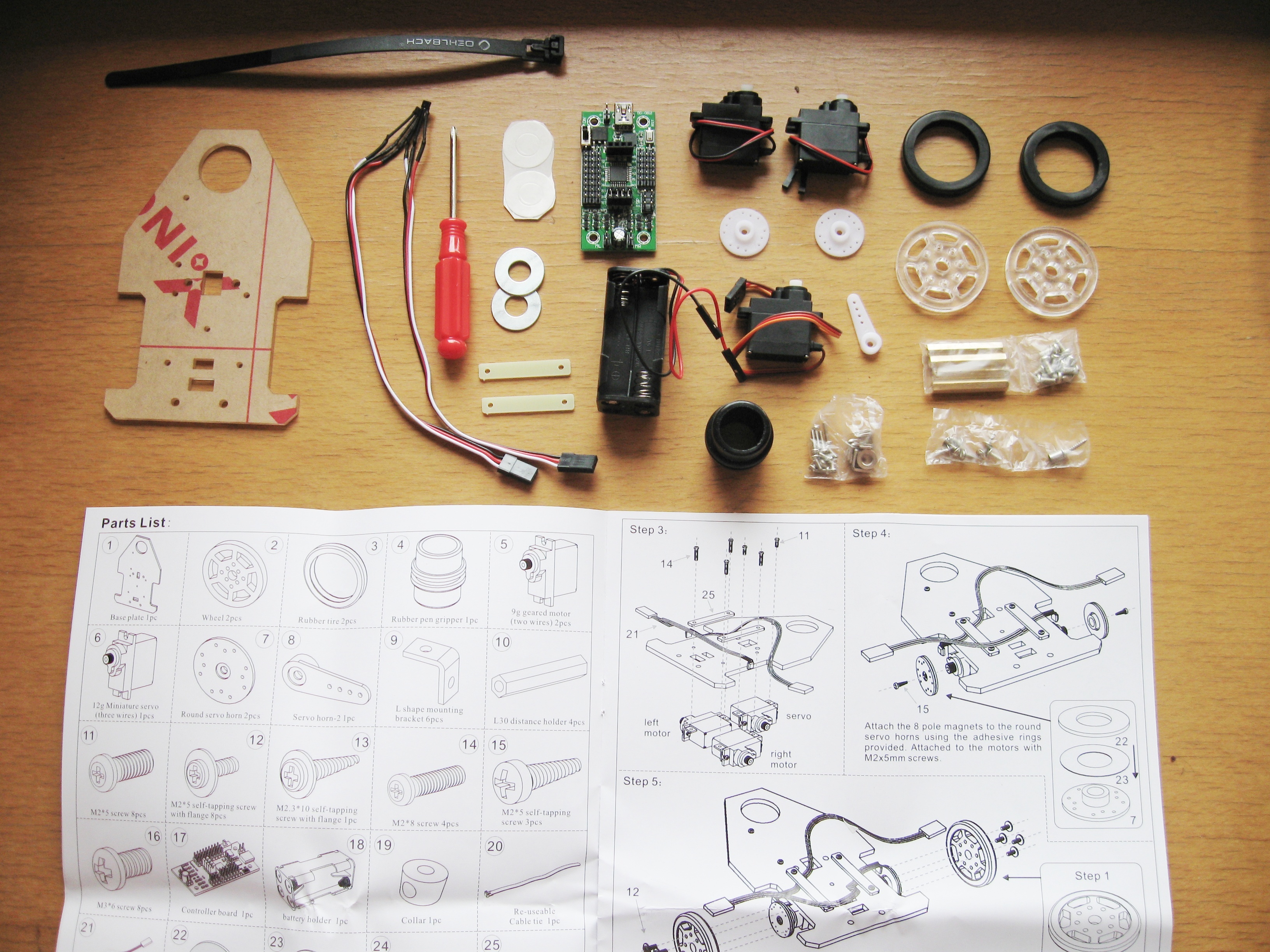
Before you begin assembly, check that you have all the parts.

In the part list, each part has a number. For example, the rubber tire is part #3. These numbers are used in the instructions to identify the parts.

The instruction manual includes printed rulers. Use these to check the length of your screws.

You can download the manual from here.

Make your wheels

Start by removing the protective film from the laser cut wheel pieces (part #2).

Gently stretch the rubber tires (part #3) over the wheels.

Identify the motors and the servo

This robot uses two geared motors (part #5) that were servos but have had their control circuit removed. These motors only have two wires.

One servo (part #6) is used at the front of the robot to raise and lower the pen. This servo has 3 wires.

Fit mounting brackets to your motors

Use the printed ruler to identify your M2x5 screws (part #11).

Partially insert six M2x5 screws into the 90° angle brackets (part #9).

Insert your mounting brackets into the motor mounting slots and gently tighten the screws until the bracket is held firmly.

Pay careful attention to the way the brackets are mounted as you have a left and right motor. The servo can only mount on the left side.

Prepare the base and sensors

Before we can build upon the base plate (part #1) we need to remove the protective film.

Our robot uses two small magnetic sensors (Hall-effect sensors – part #21) that switch on or off in response to a magnetic field. Bend their leads at roughly 90°, close to the sensor so they can hang over the edge of the base plate.

Mount your motors and sensors on the base plate

The easiest way to mount the left and right motors is to start with a single M2x8mm screw (part #14) passing through a fiberglass strip (part #25), through the base plate (part #1) and into the motor mounting bracket (part #9) on the other side. Do not tighten the screw yet!

While the screw is loose, slide your sensor under the strip as shown and then add your second M2x8mm screw. Align the sensor so it sits directly above the output shaft of the motor and gently tighten the mounting screws until the fiberglass strip bends slightly. Repeat these steps for the other motor.

Now mount the servo (part #6) using the last two M2x5mm screws.

Prepare the wheel encoder magnets

The robot has an 8-pole (4x north pole & 4x south pole), neodymium magnet (part #22) that is used to measure the distance each wheel travels. This magnet is held onto the wheel using a small ring of double sided tape (part #23).

The 8-pole magnets are only 1mm thick and very brittle. They can break easily if dropped or stressed. Handle with care.

Start by peeling away the small disc of protective layer at the center of the ring. It is much easier to do this first.

Now peel away the protective film on one side of the double sided tape and carefully align it with the magnet.

With the magnet supporting the ring of tape you can now poke the center out with the supplied screwdriver.

Repeat these steps for the second magnet.

Mount your encoder magnets on the motors

The magnets are now ready to be mounted on the round servo horns (part #7). Pay careful attention to which side they mount on (see the photo).

Peel away the final protective layer and carefully align the magnets on the round servo horns.

Now use a 2x5mm self tapping screw (part #15) to lock the servo horn in place on the motor output shaft.

Repeat these steps for the other motor.

Preparing the mounting holes for the wheels

The wheels are held on with four small 2x5mm flange head screws (part #12). These screws will only dig 1mm into the servo horn so as not to hit the magnet. To make sure they hold securely we can prethread the holes.

Pay carefull attention to which holes are used to ensure the holes in the wheel align with the holes in the servo horn.

First gently insert the remaining 2x5mm self tapping screw (part #15) into the holes to enlarge the holes. Do not go too far otherwise you may hit the magnet.

Now repeat the process with the 2x5mm flange head screws that will be used to hold the wheel on. Be careful not to push the magnet off the back of the servo horn.

Mount the wheels

Make sure your holes align well before attempting to mount the wheel. Be careful not to strip the threads as there is only 1mm of thread.

You can now mount your wheels onto the motors using four 2x5mm flanged head screws (part #12).

Align and fit the servo arm

Before we can fit the servo arm (part #8) we must make sure it is properly aligned otherwise it will not go to the position the program expects it to.

Push the arm onto the servo output shaft and gently rotate anticlockwise until the servo will turn no more.

With the servo rotated fully anticlockwise we can now fit the servo arm in the position shown using the remaining 2x5mm self tapping screw (part #15).

Mount the front roller

The front wheel (part #19) is just a simple roller made from a brass locking collar. A small brass spacer (part #24) is inserted into the collar to reduce the size of the hole. Sometimes the tin plating on the brass parts may cause the tube to be a tight fit in the collar. If so, you may need to gently press the spacer in with the screwdriver

This roller is fitted to the servo arm using a 2.3x10mm self tapping flange head screw (part #13). Pay careful attention to which side of the arm the roller is mounted on. Do not tighten the screw too far. The roller should spin freely.

Mount the battery holder

The robot is powered by 4x AAA alkaline or NiMh batteries. If you want to use NiMh batteries then you will need to modify the sample code so that the value of “lowbat” is approximately 470. This is explained in more detail in the manual.

The battery holder (part #18) is held in place with a re-usable cable tie (part #20). Thread the cable tie through the holes in the base plate as shown with the head at the back of the robot.

Insert your battery holder (you may want to install your batteries first) and tighten the cable tie gently so that the battery holder cannot fall out.

When you need to replace the batteries, simply press down on the small lever on the cable tie head to release the catch and loosen the cable tie so that the battery holder can slide out. Install fresh batteries and re-tighten the cable tie.

Fit the controller mounting spacers

The robot control PCB (Printed Circuit Board – part #17) is mounted above the battery holder using 4x 30mm brass spacers (part #10). The spacers are mounted on the base plate using four M3x6mm machine screws (part #16) as shown in the photos.

Do not over tighten the screws! The base can crack if excessive force is used to tighten the screws. You only need to tighten the screws firmly so that friction prevents them from coming loose.

While the robot is upside down, now is a good time to feed your motor and servo cables through the hole at the front if you have not done so already. There is a spare hole at the back in case you wish to add other sensors in the future.

Mount the controller and install the rubber pen grip

Use the last four M3x6mm machine screws to mount the controller on the brass spacers with the USB (Universal Serial Bus) socket at the rear of the robot.

Press the rubber pen grip into the hole at the front of the base plate. Although the rubber grip was originally designed for thick whiteboard markers and permanent marker pens it can also be used for jumbo chalk and crayons.

Try inserting two or three small crayons or chalk sticks into the rubber grip for a rainbow effect. If you have a whiteboard marker or pen that is a little bit too small for the grip then wrap some layers of tape around the pen to make it thicker.

A quick tour of the Mini Driver PCB

The Mini Driver is a low-cost robot controller that is ideal for beginners. The controller is compatible with an Arduino NG with ATmega8 and is easily programmed using the free Arduino IDE.

Unlike standard Arduino boards, the Mini Driver is specifically designed for small robots and has a dual motor controller built in that can drive 2x D.C. motors (2 amps each) or 1 stepper motor.

The digital pins are terminated in a 3-pin male header that allows up to 8 miniature servos to plug directly into the PCB and be powered directly from the battery.

Power and ground pins are also included with the analog inputs to provide power for sensors.

Reverse-polarity protection is built into the board so that accidentally swapping the power wires will not damage the board. Input voltage is 5.5V to 10V.

Wiring up the robot

Doodle Bot has 2 digital sensors and one small servo that will not be under heavy load so we need to set V+ to 5V to prevent damage to the digital inputs.

Next we need to connect the motors. You can see on the control board that the motor outputs are labeled “ML” and “MR” for motor left and motor right. In the case of Doodle Bot, the “ML” output is on the right side and the “MR” output is on the left side. This is so that the USB socket is to the back of the robot.

Connect the right motor to the “MR” output and connect the left motor to the “ML” output. Pay careful attention to the colour of the wires. When the robot runs the sample code the first move it should make is to travel forward a short distance, then back up and turn anti-clockwise.

If either motor runs backward at the beginning of the sample code then that motor needs to have its wires swapped over. Once the robot has gone forward and then reversed a bit, If the robot first turns clockwise then you need to swap left and right motors.

Make sure the power switch is in the off position and connect the battery holder as shown. The controller has reverse-polarity protection so if you accidentally connect these wires the wrong way the robot will not be damaged. it just won’t turn on.

Wiring up the robot (continued)

Now connect your wheel encoder sensors and the servo. Note that the black/brown wire always goes to the outside of the PCB. The white or yellow wire is always closest to the processor.

Make sure your right wheel sensor connects to D2 and your left sensor connects to D3; otherwise the robot will end up running around in circles with one motor stopped and the other motor running continuously. The servo connects to D12.

Programming

The manual contains detailed instructions for uploading the demonstration code into the robot. However, printed links to the software are difficult to click a mouse on and a pain to type.

To begin with you will need the Arduino IDE to suit your operating system (Windows, Mac OS X, Linux 32 bit or 64 bit). You can download the Arduino IDE for free from here.

Do not download the latest version as the code won’t compile correctly and even if it did, the new versions compiles into a larger file that may not fit the limited space of the ATmega8A.

The sample code was written in version 0022 of the IDE. You may find it compiles slightly smaller in version 0018 if you’re running low on memory.

You may also need to download USB drivers for the CP2102 interface. You can download the latest drivers for your operating system here.

Once you have the Arduino IDE running on your system you can download the sample code from here. You can then make the robot print any message you want following the instructions in the manual.

What's next?

The Doodle Bot is not limited to just pushing a pen around all day. It is a perfect platform for any small robot. Add your own sensors, a small gripper, write new code for it.

If you need more memory then the Mini Driver can be replaced with a Micro Magician which includes more memory, a 3-axis accelerometer and an IR receiver.

Join a website such as Let’s Make Robots and you can learn from and share with a community of fellow robot builders.

Conclusion

Once you have assembled your robot, all software and sample code can be downloaded for free from the internet. By joining a website like Let's Make Robots you can then get help and ideas from fellow robot builders.