Additional Materials Required:
- The Prepared U-Channel
- Wide Cylinder Supports
- 3/4″x2″ Bolts (16)
- 3/4″ Galvanized Nuts (16)
- 3/4″ Washers (16)
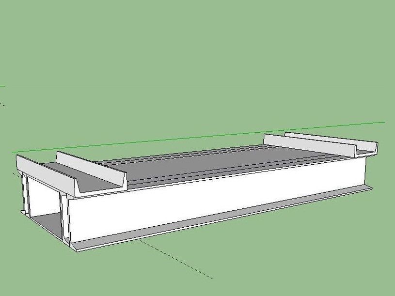
Assemble the U-channel on your Compressed Earth Brick Press.


Gather materials for the “Jig”; this means 6”x12” tubing (52”) and any extra heavy U Channel. If you don’t have any laying around, you can use one drawer member, and one spacer on each side.
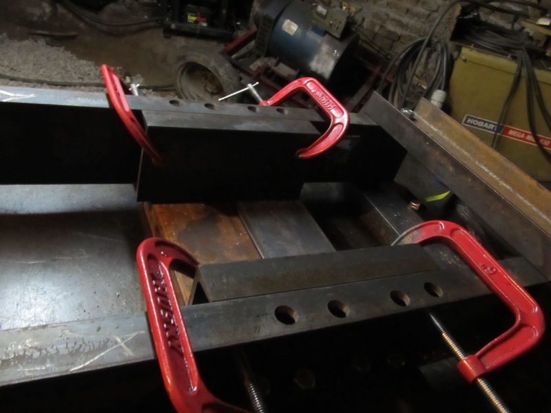
Clamp the vertical pieces to the “Jig” on each end, with extra U channel in between the tubing and the vertical pieces.
Make sure they are both orientated properly, that is that both roller slots are at the same end of the jig.
Insure the two verticals are flush at the top end.

Clamp one horizontal member at each end of the jig.
Make sure they are flush with the ends of the verticals and centered on them.
Insure they are square with the jig by using a large square.
Clamp using 1 or 2 vise grips on either side.
If you didn’t need to use the drawer members for the jig, you can drill those and the wide cylinder support holes now too so you won’t have to handle the material twice. See below for how to do it.
It really helps to label each member, so that if you end up unbolting the piece later, you’ll know exactly where it goes and in what orientation. Mark which side will be the top of the machine, and which member goes where.

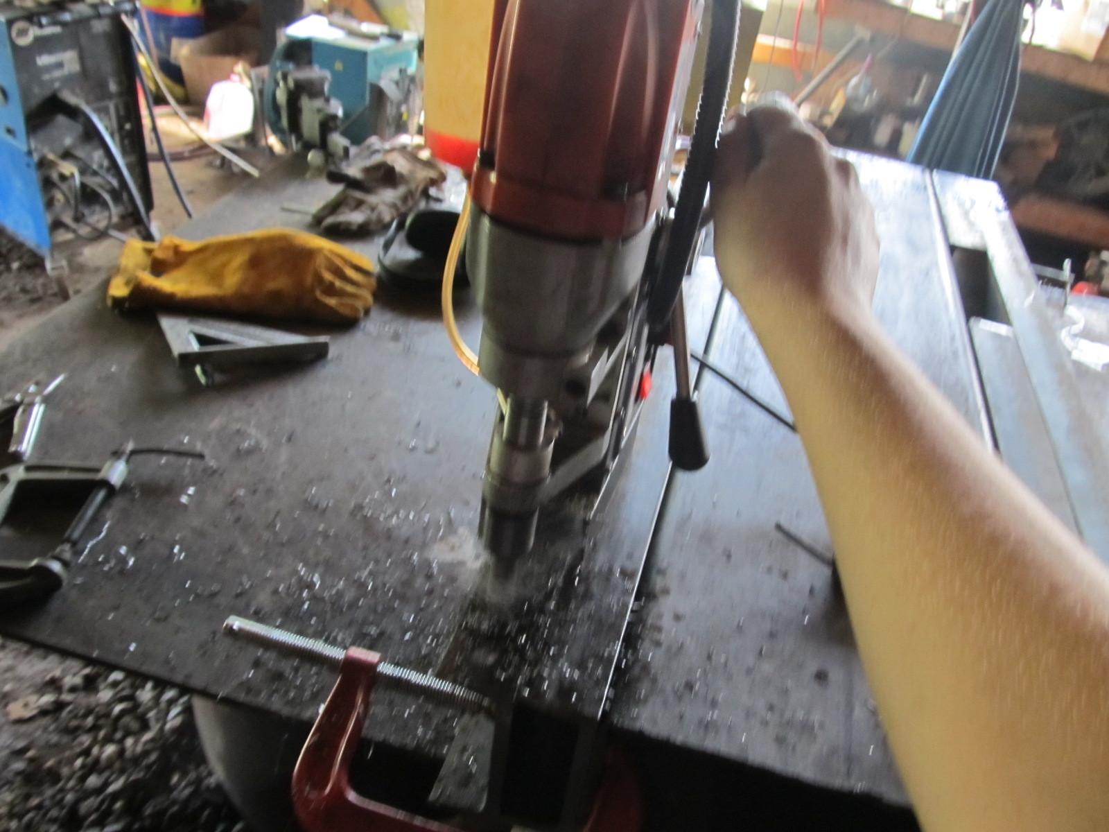
Use a Mag-Drill to drill the 3/4″ holes each place where the horizontal members overlap the vertical members.
Before drilling, double check that when the holes go thru the vertical members, they will be on the lip of the U-channel, not going into the wall, or off of the lip.
Bolt the horizontal members tightly to the vertical members.
Flip the jig over so you have access to drill the other holes. See video for help.

Clamp the other 2 horizontal members in place.
Align the other horizontal members with the ones below the jig, so that they are both at the same location relative to the vertical members.
This is crucial so that the machine will stand up straight and there won’t be any gap between the drawer and the top horizontal members.
Insure once more that they are square with the vertical members.
Mag Drill them.
Remove the clamps and the jig from the frame.
Bolt the horizontals tightly to the frame.
Double check to make sure everything is still square.
If not, loosen the bolts and square it up on what you labeled top first and tighten those bolts. Then square out the other side and torch out any spots prohibiting the bolts from going thru.
Bolt it back when you’re done.

Clamp the drawer member centered, 7″ from the upper cross member.
The drawer slots should be on this side, not opposite.
Make sure the adjustment nuts are facing where the drawer was, look at the picture.
Clamp the wide cylinder support adjacent to it.
Make sure you label each component for re-assembly later.
Mag-Drill 1″ holes at these centers.
Don’t bolt these yet, you’ll do that later.

Place the 1/2″x3″x24″ flats on the drawer members centered as shown.
Weld them in place, using about a 50% weld.

Note: You not welding them because when you stretch the frame, it may “move” their location.
With the frame laid down, and one of the drawer members under it to support the spacers, place the spacers on each side.
The end of them is to be 7 1/32″ away from the upper cross member. Look at the diagram.
Insure they are parallel and flush with the U-channel and C-clamp in two places for each.
Tack them on this side in 3 spots.
You may need to grind this off later, so make sure the tacks aren’t longer than 1/4″ or so.
Flip over the frame and tack the other side.

Put the dirt blockers in place, between the vertical members, so the bottom side of them is about 1/8″ above the bottom of the upper crossmembers.
Weld the portion inside of the vertical members, taking care to not weld them to the crossmembers.