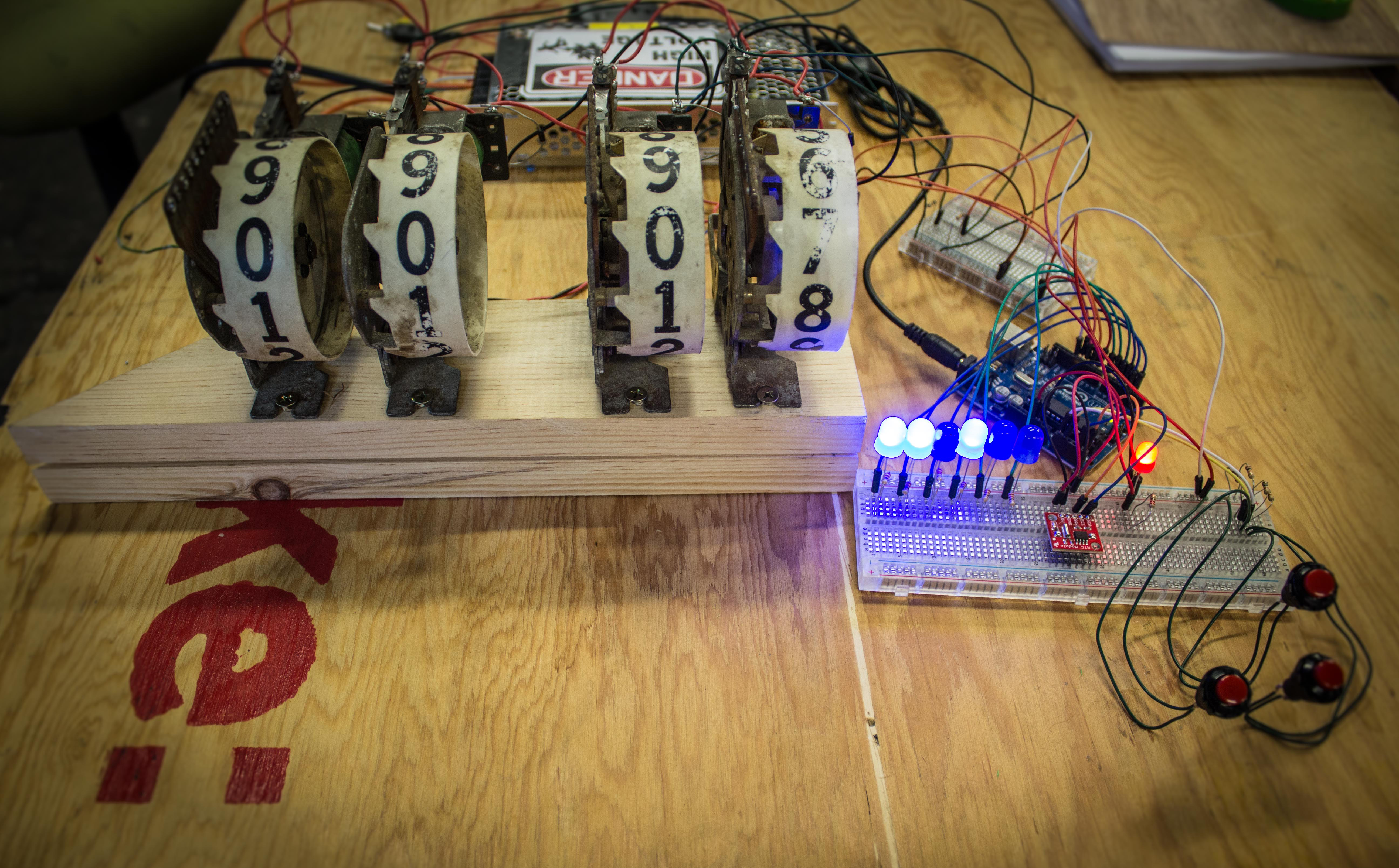
Pinball Clock Main

Solenoids (a type of electromagnet) are at the heart of pinball machines, and at one time, many other machines. They work by inducing a magnetic field using a coil of copper wire. This makes them ideal for pushing or pulling mechanical things fast and with force.

They have become unnecessary over the years in most applications with the advent of more precise motors such as servos and stepper motors. They are also no longer needed for computation or high voltage/current switching, as we now have semiconductor based components. Semiconductors are much more reliable, last longer, and are more ideal in some cases since they have no moving parts and as a result create no noise in their operation.  But they don’t have the cool steampunk like nostalgia that solenoids have with their copper coils, clicky sounds, and epic power supplies!

Now, these magnificent components are becoming extinct. Let’s preserve some electro-mechanical pinball history with this project, where we use old pinball score reels to display the time. Also, since no maker clock is complete without some use of binary, our clock is going to give us a readout of the seconds in that form.

Since this project uses a lot of pins, we are going to do some things to make sure we don’t use all of them.  Hey, you never know what you might want to add.

Project Steps

Prepare reels

Before we get down to the meat and potatoes of this project, we should clean up our historic parts so they look nice and organized.

If your score reels have any old nasty wires attached to them, remove them so we don’t have a rats nest of wires in our way of understanding how to wire the reels up properly and how the circuit works.

As these reels are old, you should clean the contacts for all the leaf switches with an old toothbrush and rubbing alcohol.

Another use for the rubbing alcohol, and old toothbrush (or q-tip), is to clean off the reels of old dust and grime. This is often some nice work-free weathering.

Make a reel holder

One thing that will make the process of soldering all the wires on the reels simpler is a holder to hold the reels while you’re running your wires.

You can make one simply by drilling screws in some wood leaving enough room between the reels for them to operate properly.

Locate end of travel leaf switches for triggering a second digit

We need to connect two reels together to give us the ability to display two digit numbers. To do this we are going to use two of the leaf switches our first digit reel has: the solenoid end of travel and 9 position.

Look at the leaf switches on your first digit reel: the solenoid end of travel switch may be set to be normally close (Image 2). We need it to be normally open (image 1). If so simply unscrew, flip, and bend the leafs so they only touch (close) when the solenoid is pulled. You may need to move the spacers that are apart of the switch to the other side of the stack.

Wire up solenoid end of travel leaf switch for triggering a second digit

In order to trigger the second solenoid properly, we first need to connect the + for our second reel’s solenoid to first’s end of travel switch.

Locate 9 leaf switches for triggering a second digit

One side of the end of travel switch then connects to the 9 switch. This switch is closed when the reel is on the number 9.

The other side of the 9 switch must connect to the + on our first digit reel’s solenoid. The grounds of both reels can be connected together.

Locate leaf switches for detecting zeroed reels

In order to make sure we are displaying the correct time and not using too many Arduino pins in the process, we need to calibrate the reels at boot and every 12 hours (24 if using military time).

On our reels, these leaf switches are open when the reel is at zero and since we have two digits we are going to wire up these switches in parallel so we get a sort of logic “and”. This way the Arduino only sees when both digits of the reel are at zero.

Solder two wires one for each side of the switches to connect later to the Arduino.

Add the clamping diode to all solenoids

Solenoids use a copper coil to generate a magnetic field. When one removes the power, that magnetic field collapses and generates a high voltage spike.

This spike is a big annoyance to digital electronics such as Arduinos. To combat this we add a diode, called a Flyback diode that shorts out the solenoids coil in one direction, so this spike has no effect. The white stripe of the diode points in the direction of the current flow.

Repeat steps 3-7 for the hours reels.

Connect the two reel pairs to the relay board

Connect the + wire for our minutes solenoid to one relay and the hours solenoid to the other.

Date time set button input

Since we don’t have very many inputs/outputs on the Arduino we are going to do a clever little trick to kinda get extra input pins.

First, you need to make a voltage divider. Get two 1KΩ resistors and wire them up in series; then connect them parallel with the GND and +5v. Now, we have a nice voltage divider for us to use in our logic.

Connect one side of the down button to the middle of our voltage divider, then the other side to Analog 0 and a 10kΩ resistor to ground.

Connect one side of the up button to the top of our voltage divider (A.K.A. +5V), then the other side to Analog 0. This button doesn’t need a resistor since there is already one on this analog pin (so both buttons can share a pull down resistor).

This circuit will give us half voltage when the down button is pressed and full voltage when the up button is pressed. The only problem with this circuit is if both buttons are press we get full voltage and, thus, the Arduino can only tell the up button is pressed. Luckily pushing both buttons isn’t necessary to setting the time properly.

Connect one side of our set button to +5V, then the other side to Analog 1 and a 10KΩ resistor to ground.

Seconds & am/pm LED output

Connect the + pin (long lead) of an LED to digital pin 2. Connect the GND pin (short lead) of the LED through a 220Ω resistor to ground. Do this for all 6 LEDs, pins 2-7.

For the AM indicator LED, connect the + pin (long lead) to digital pin 9. Connect the GND pin (short lead) of the LED through a 220Ω resistor to ground.

Real Time Clock (RTC)

This RTC uses I2C to communicate so this saves us even more pins. Connect the RTC’s SDA (Data) to analog 4 and the SCL (Clock) to analog 5. Don’t forget to also hook-up the RTC’s power.

Wire up the Arduino to control the relays that control the reels

Connect the relay board’s control pins to 10 and 11 (these are the minute and hour pins). Don’t forget to also provide the board with 5v power.

Wire up the reels zero switch to the Arduino

Remember, the 2 wires we soldered to the zero switch of both the hour and minute reel pairs make a total of 4 wires, now we will be connecting them for input!

Johnny5 “NEED INPUT!“

Yes Johnny5 INPUT!

Take one wire, doesn’t matter which, from your minutes reel pair and connect it to +5v. Connect the other wire for this pair to pin 12 and add a 10KΩ resistor to ground. Do the same for the hours reel pair, but connect it to pin 13 instead.

Disassemble the 9V supply

This supply is super easy to disassemble; all you need to do is unscrew the screw towards the end on the bottom of the supply. Once open, all you need to do is disconnect the wires connected to the plug.

You may wish to lengthen these wires, to do so just un-solder them from the board and solder on new longer, red and black, 16 gauge wires. These wires will connect to the screw terminals of the other power supply.

Wire up the cord for the power supplies

WARNING: HIGH VOLTAGE ELECTRONICS!
This step has a danger of electrical shock. Do not do this alone.

Take the 3 prong electrical plug, making sure it’s not plugged in, strip the end of the cord and the three wires inside. Connect the neutral (white) to the 35V supply’s neutral (N) screw terminal. Also, connect the ground (Green) to the ground screw terminal which is to the right of the N terminal.

Mains power switch

You could always just wire the cord directly to the screw terminals (which is safer), but if you are good at electronics and have flown through this tutorial you can probably pull this off. Adding a switch will save you the hassle of unplugging the thing when quiet is needed.

Solder the hot (black) wire of your cord to your power switch and add heat shrink. Solder the other end of our switch to a red 16 gauge wire, add heat shrink, and connect that wire to the hot (H) screw terminal on our power supply.

We are wiring the power switch to turn off and on the hot line because the neutral line is at the same voltage potential as ground. (DO NOT ATTEMPT) This means that if we touch the circuit when the switch is off we don’t get shocked. If we didn’t switch the hot and switched the neutral instead the circuit would still be live with 110V AC. Now, the circuit wouldn’t operate properly since it’s an open circuit but it would still be a shock hazard.

Anytime you are working on this circuit make sure it’s unplugged.

Remember to heat shrink all the mains connections. Also, I added a wire to ground out the metal toggle switch. When working with mains it’s a good habit to get into (grounding out metal). The reason we do this is in the event a mains wire becomes loose and touches this metal. Instead of making it a live shock hazard it just trips the breaker or GFCI which ever it’s connected to.

Connect the 35V supply to the relay board and relays.

Using a pair of red and black 16 gauge wires, tin and connect the screw terminals on the power supply to the relays and solenoids.

I wired in a fuse so if the solenoids somehow get stuck on they don’t melt themselves. I would hate for my reels to break. You probably need to experiment with different size fuses. My reels draw an amp each (at most we are only powering two reels) so I suggest starting with a 1amp slow blow fuse.

Download the code and upload to the Arduino

Almost finished. Now, you just need to download Pinball_Clock.ino and upload it to the Arduino.

To set the time, hold down the set button until all the seconds LEDs light up. The reels will zero and then display the set hours. Using the up and down buttons, set the correct hours. Press the set button to advance to the minutes, then seconds.

ENJOY YOUR NEW EPIC CLOCK!

Conclusion

Next week we will build a custom enclosure for the clock that proudly displays the handiwork, and the mechanics of this clicky, clock.Feel free to add features to this project. You could always make improvements like adding a serial screen to display the date/time info not covered in this project such as year, month, day, and week day. Another idea is add an alarm function or have it notify you of emails.