conky5

YouTube player

You probably already know the Arduino is a cool prototyping platform which allows you to build great projects with minimal effort. Over the years many contributors have designed compatible hardware and software libraries for easy methods to interact with the Arduino.

With the Crittergram Capture Cam we’ll combine several common components to create a camera that only takes pictures when critters move in front of it.

The Hardware

In this project we will connect the JPEG Camera module from RadioShack to the serial port on the Arduino Uno. We’ll also use a PIR (Passive InfraRed, learn more) sensor to detect motion. And lastly, we’ll use an SD card reader to provide storage for saving our images (the SD card doubles as a fast and easy way to transfer images to the computer).

If you look at the specifications of the camera module, you may notice it has a built-in motion detector. So why not use this instead of the PIR? Well, the camera module detects motion by changes in the image, so that a branch moved by the wind would make it take a picture. The PIR sensor works similarly, but by analyzing the infrared spectrum which is invisible to the human eye. That means it will only trigger if things are hotter (or cooler) than the general surrounding IR spectrum. Humans, most animals, even moving cars will trigger the PIR, whereas a swaying branch will not (this way we don’t end up with a memory card full of the same scene).

The Software

We’ve rated this project’s difficulty as easy due to the plug-and-play nature of the modules and the software provided. Essentially this project combines several pieces of software into one, including some of RadioShack’s provided sketch code with their JPEG Color Camera, modified to suit this build. See Steps 4 & 5 below for a verbose explanation of some of the routines and sub-routines used in the Crittergram Capture Cam sketch code.

You could easily take this project to the next level by turning it into a webcam (see conclusion), modifying the sketch code to take time lapse shots, or implementing an LDR or other method to take daytime-only shots, etc.

Sketch Code

Download the Arduino .INO sketch from MAKE’s GitHub: https://github.com/Make-Magazine/Crittergram-Capture-Cam

Project Steps

Format the SD card

If you are not using a new SD card, make sure you don’t have any files on there, because when we format it all the files will be erased. Insert the SD card into the slot on the SD card shield, and connect the shield to the Arduino. Make sure your pins line up correctly.

Download the sdfat library and install according to the included readme file. We are not actually going to use this library, but it comes with an example “SDFormatter” sketch, which we will use to format the SD card.

Now you can connect your Arduino to the computer. Then open the SDFormatter sketch from the menu File -> Examples -> SDfat. Upload the sketch and open the serial monitor to initiate. Confirm by sending Y for “yes” and then F for “erase and format.” If there are no error messages your card will be formatted (this also ensures the Arduino is properly connecting to the SD card shield).

Prepare the modules

The JPEG camera comes with a quadripolar cord which we use to connect to the Arduino. Connect the female plugs to the module. The red wire connects to +5V, black to GND, brown to RXD and white to TXD.

For the PIR sensor, you will need 3 jumpers cables, also female to male. Again, connect the female plugs to the PIR sensor. The red wire connects to VCC, black to GND, and the blue wire connects to OUT.

Put everything together

Just to make sure nothing bad happens, unplug the Arduino from your computer.

NOTE: The illustration shows the modules plugged directly into the Arduino. Your pins will actually be plugged into the SD card shield. The I/O pins are the same if the shield is correctly aligned atop the Arduino. (For example in slide two the camera’s 5V and GND pins are plugged into the SD card shield.)

Hook up the PIR sensor by connecting its GND, VCC and signal OUTput to GND, Pin 8 and Pin 7 on the SD card shield. The PIR module has a jumper labeled “S” & “L”. Use it in “S” or “short” mode for sensing 15′ or less, and “L” or long mode for sensing 15′ – 30′.

Take the time to read over the JPEG camera module’s manual. When you’re ready you can install the module: connect Power (5V and GND) to their respective inputs on the SD card shield; follow the serial connections as illustrated (NOTE: the brown cable on the camera module connects to RX which connects to TX on the shield, and vice-versa for the white cable – this is all accounted for in the sketch code which we will examine later).

Reconnect the Arduino to your computer and open the sketch provided in the introduction.

To properly upload the sketch to your Arduino, disconnect the RX/TX wires temporarily from the SD card shield and the hit the upload button in the Arduino SDK (if the RX/TX wires stay connected you will get a generic upload error). After a successful transfer, reconnect the RX/TX wires and press the reset button on your Arduino once. Crittergram Capture Cam will boot up and start taking pictures after a few seconds. To access the images taken, simply unplug the Arduino and eject the SD card by firmly pressing it into the slot (it will pop out thereafter).

Sketch Code

The first paragraph of instructions is related to the camera module. Most of what is in there are definitions of hex-code instructions (all those 0x## values), which makes it more readable for humans. If you read the names of those variables it will tell you what they can be used for. A few of them aren’t used in our code, but that’s okay. Should you add code from the RadioShack examples, then it’s all there (similar to how the original RadioShack code was modified for this project).

Next, we have a few instructions and variables which relate to the SD card module. It doesn’t matter whether you use the SD card shield or the SD card reader on-board the ethernet shield (see Step 8), just make sure the value of SdChipSelect is defined according to your setup. myFile is the handler for our SD card access, while myFileName and myFileNr are used for storing the current filename and a counter (so it will record in ascending filenumbers onto the card).

The setup() routine is called once by the Arduino after booting up. First, it will begin to access the SD card, using the the pin number stored in the SdChipSelect variable.

Serial.begin() opens communication on the Arduino’s dedicated serial port, with a speed of 115200 baud/s, which is the default baud rate of the camera module, and also the maximum speed available on this port.

After opening the port, the program sends the first command to the camera. The VC0706_compression_ratio() subroutine is called, with the argument 66. Why sixty-six you ask? And what is VC0706? The way this camera module works is to attatch a NTSC camera (hence the 640×480 resolution) to an Integrated Circuit (IC) called the VC0706, which allows us to freeze a video frame, compress it to JPEG and read it out digitally. And it will do that with the quality index of 66 (out of 100, or roughly two-thirds of the maximum quality) which we just instructed it to use.

The Loop

The loop() routine contains the code for the intended use of the camera. If you like to, this is where you can start modifying the code to accommodate your own needs.

You’ll find a while loop, which will run and count up in the variable myFileNr for as long as it finds files on the SD card. Once it counts to a number with no corresponding file, it will break the loop and proceed with the program. This means it will never overwrite an existing file, even if you delete files in between. Be advised that deleting single files will disrupt the order of images taken, as all the files have the same creation date. This is due to the lack of a real-time clock in the Arduino, but nothing stands in your way to add one to the project.

Next, there is another loop, which basically let’s the Arduino wait while the PIR sensor is not triggered. The voltage level on the digital input pin 7 is LOW in normal state, and turns HIGH once the sensor is triggered. The Arduino will check for that with a millisecond break in between.

Once the program exits this waiting loop, it will immediately take a picture. It does so by calling the capure_photo() subroutine, supplying a filename stored in the variable myFileName (determined in the previous Step).

All the subroutines following loop() are taken from RadioShack’s sample code, with some modifications to the capture_photo() routine. The most obvious change to the original code is that we can specify a filename for the photo taken. If you want to start using the camera in your own projects, I recommend to copy “camera stuff” and “sd card stuff” from the beginning of the code, and all routines following the loop() routine. You can then call capture_photo() from anywhere in your code.

Crittergram Housing

Now put your project into an enclosure of some sort. We took the chance to explore RadioShack’s new Project Enclosure Skeleton Kit with pre-drilled holes and cutouts (image 1). Depending on if you plan to place your Crittergram indoors or outdoors you may need to weatherproof your project.

Also depending on where you wish to place your Crittergram you can use different power sources. If your Crittergram is placed indoors you could easily connect the Arduino to your computer via USB or use an adapter plugged into a wall outlet. If you want more flexibility for where to place your project, you could use a mobile power pack, as long as the voltage output matches the power required by the Arduino.

Tidy up your cables with zip ties and use Supermount tape or hot glue to affix your modules into place on the enclosure’s plexi.

TIP: Learn more about powering your project on the Arduino website; also see this 9V adapter mod for inspiration.

Another TIP: The skeleton enclosure kit allows you to strategically arrange all your boards, shields, and modules. You can then place the enclosure kit into whatever housing unit you have available, and all you have to do is drill two holes for the camera lens and PIR sensor to poke out (image 3). Ideas include placing the Crittergram in a birdhouse, camouflaging it inside a hollowed-out log, or building it into a book to hide on your shelves.

Capture Critters in the Act!

Is a neighborhood critter terrorizing your garden? Do you suspect one of your pets is eating another’s food? Has your pooch found a way to sneak extra snacks without you knowing it?

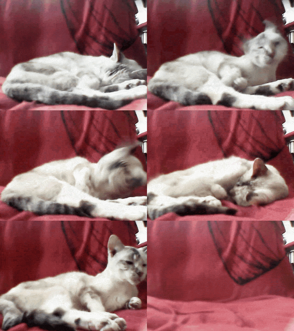
If you suspect a critter then capture them with the Crittergram! Be sure to upload your pictures or GIFs (like ours) and tag them #crittergram on Facebook, Google+ or Twitter – we’ll be watching. Or emails your pictures to weekendprojects@makezine.com.

Conclusion

The Crittergram is a quick Arduino-based solution to build a VGA-resolution motion-sensing camera. Use a portable power pack and your project could be left alone for hours or even days.This project shows how you can easily combine shields and modules with the Arduino. Additionally, we've combined several pieces of software into one to suit our specific needs. This project can be easily modified or expanded upon (such as turning the Crittergram into a remote webcam, see below) for a novel Weekend Project of your own design.

Next Level: Remote Crittergram (using an Ethernet Shield)EthernetShield_bbSo how can we make it better? Let's hook up the Crittergram to our local area network, or even the internet! Arduino provides a shield, which comes with a web server built in. It also has a slot on-board to add a micro SD card. Once the ethernet shield is connected to your Arduino, you only need to hook up the camera and the PIR sensor, the same as described in the steps above. The pins needed are all being connected through the shield, the same as if you would plug it into the Arduino directly. If you are using our demo code for the webserver, please change the IP and MAC address, located in the first few lines of the code. Keep in mind that the sketch first saves an image to the micro SD card and then, when a client requests it, loads it again from the card- this means there are a few seconds delay between the image being taken and displaying on the computer requesting it.