Photo by Brian Mernoff

When I look to begin making a new model, I look for two things. First, the subject matter must be something I’m excited to learn about. For me the design process is more about learning about the objects and topics in detail than the final product. Second, the project needs to present a design challenge I haven’t encountered before: the need to design a new mechanism, a complex shape I don’t know how to model, or a new tool or technique I haven’t tried.

This article appeared in Make: Vol 81. Subscribe today for more robot projects and tips.

The James Webb Space Telescope (JWST) was a perfect combination of these factors. I have always been a huge space fan and had been following the progress of JWST for years. As the launch approached, I thought about designing a new JWST model but hesitated, because I had already designed a smaller one as part of my Space Telescope Chess Set several years ago. This changed after the launch when I began to follow the telescope deployment steps on NASA’s “Where is Webb” webpage. I’m a huge Transformers fan, and what I was watching was pretty much a real live transformer — I had to figure out how to make a model that transformed in the same way!

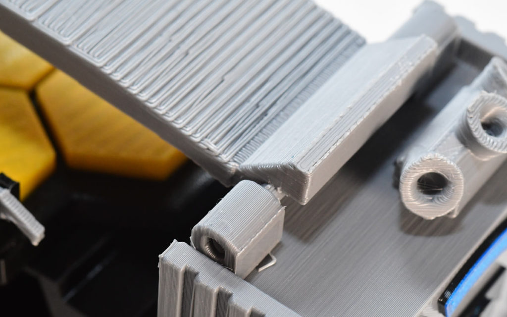
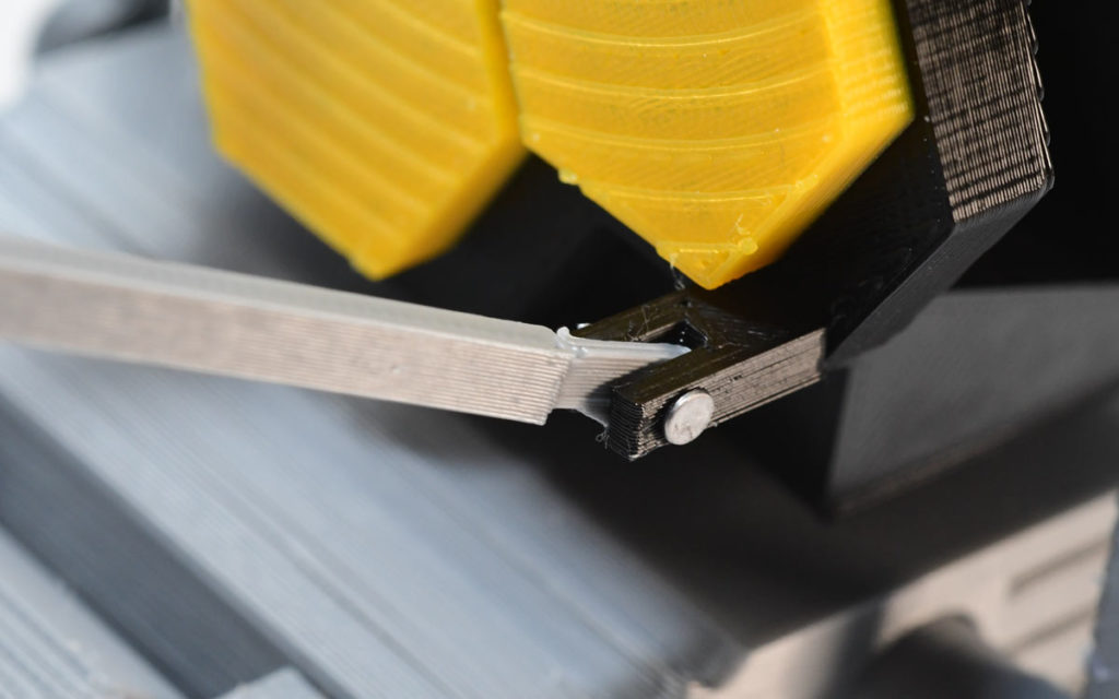
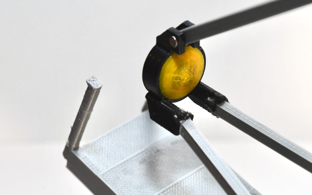
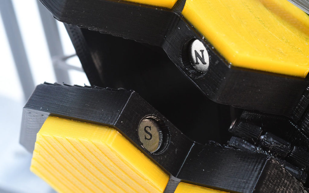
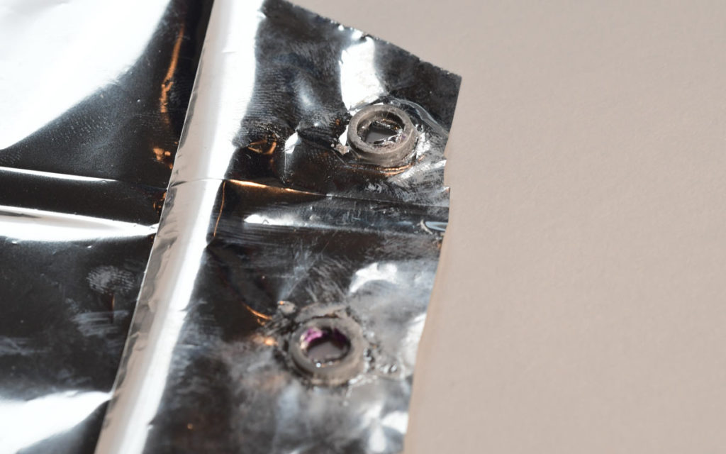
Once I know what I want to build, my design process begins with initial research and a design phase in my head. I found resources containing schematics of the telescope and detailed videos and websites describing the deployment steps. As I learned about these steps, I started to think about different mechanisms and ways that I could accomplish the needed movements. My hour-long commute to work was filled with me iterating different methods to create new hinges, move the secondary mirror assembly, and deploy the sunshield. Once I had a fairly solid idea of how the model could work, I then started my CAD design phase.

YouTube player
Prusa published a great video showing some of the building steps.

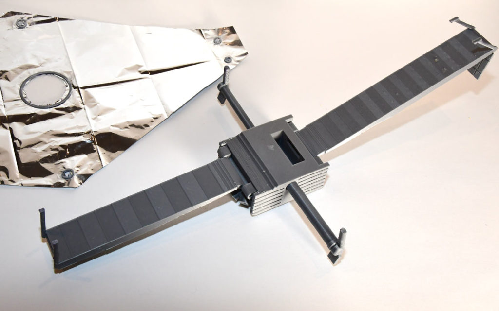
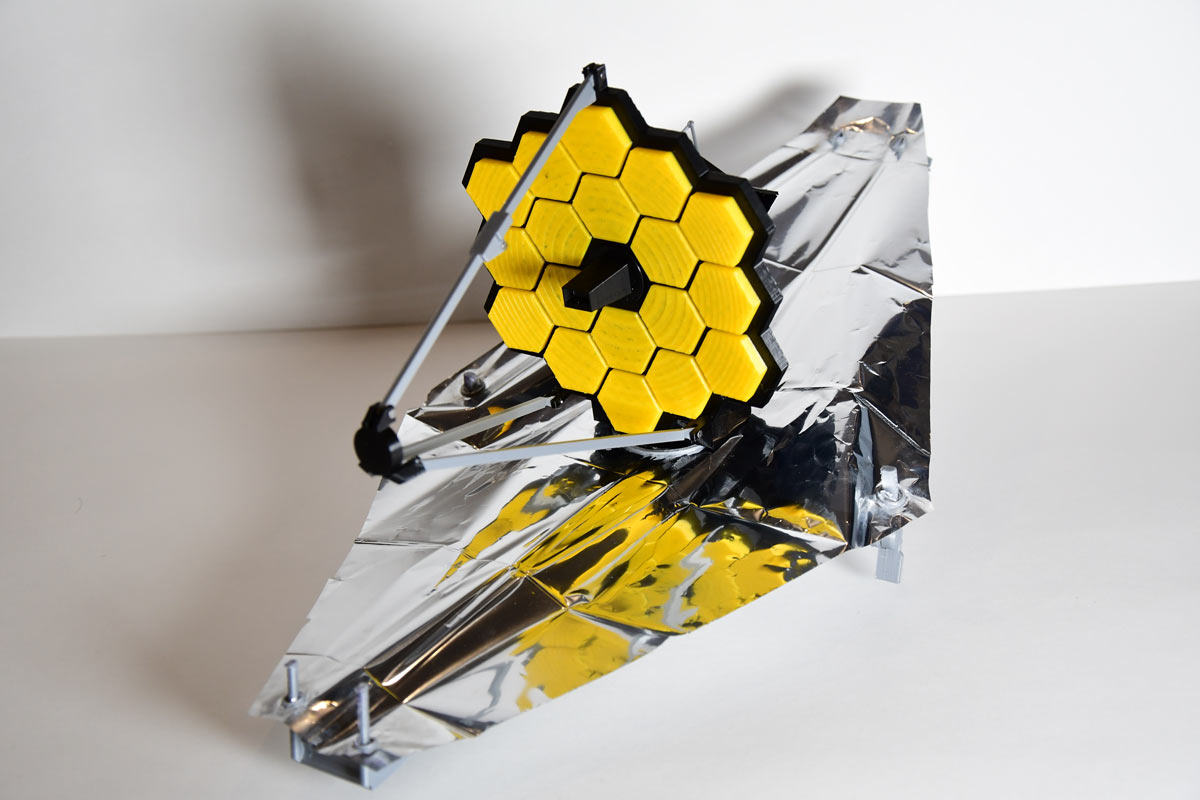
The model was done! The final model measures approximately 40cm×22cm×18cm and can perform deployment steps including:

  • Solar Panel
  • Antenna
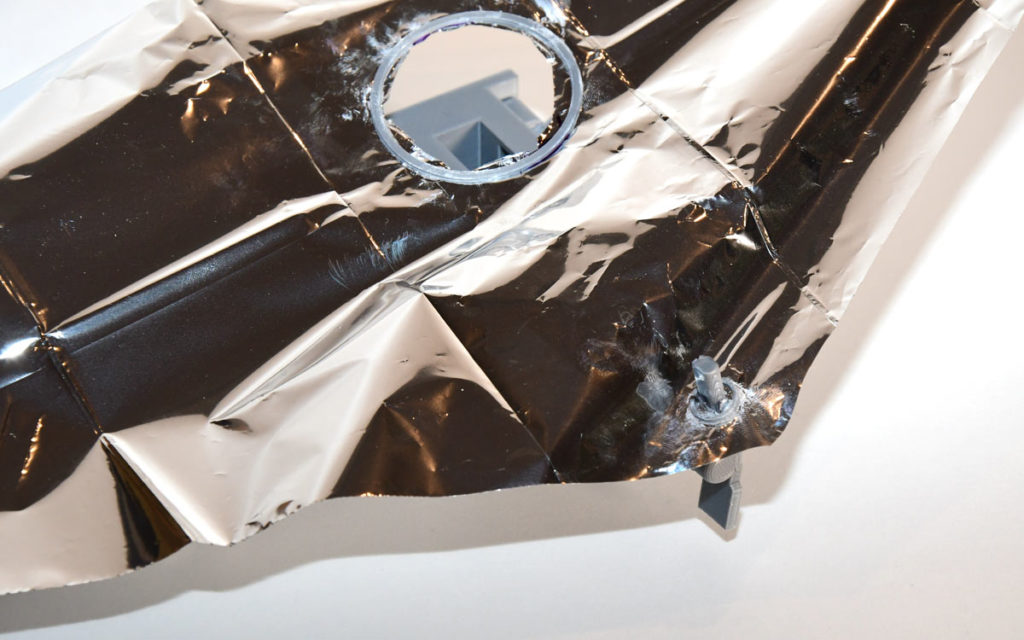
  • Fore and Aft Sunshield Pallets
  • Left and Right Sunshield Boom Extensions
  • Aft Momentum Flap
  • Tower Deployment
  • Secondary Mirror
  • Radiator Panel
  • Primary Mirror Wings

I have now posted the model on several 3D printing model sites, with instructions for assembling it. I enjoy contributing to the 3D printing community since I have learned so much from the open source resources that so many people create. Therefore, if I post a model, I want it to be accessible and freely available to as many makers as possible to build, modify, and share. This is especially true of the educational models that I designed for myself and other educators to use with their students. I hope that anyone who builds the JWST model will learn as much as I did in the process and that maybe it will encourage others to explore science and engineering.

Since this model requires several non-3D parts and assembly steps that were not simple to explain, I was hesitant to put it out there at first. It has been quite a while since I’ve shared any models online as my designs have begun to include laser cutting and post processing steps that are fairly complex. After receiving so much positive feedback from those that I shared the model with in person, I eventually decided to share it online, which turned out to be a great decision. I am now starting to rethink posting some of my unreleased models such as my camera puzzle box, watch charging stands, and Perseverance/Sky Crane lamp. You can keep up with my designs on Thingiverse.

Project Steps

Using Fusion 360, my first step is to determine the overall size of the model. I do this by finding the smallest component that will be needed to be printed on the model and making sure that it will be big enough to print.

For this model, the limiting structure were the hinges. Unfortunately, the very large size of the sun shield, compared to the rest of the telescope, presented a challenge as the parts needed to fit on my Prusa MK3S printer. This led to a compromise of scaling the hinges so that I needed to use nails, instead of filament or printed parts, as the axles.

Once I have the size, I import a schematic into Fusion 360 and scale it to match my plans. I then create the basic outlines of the different parts and work through the model building the mechanisms first. It’s easy to get wrapped up in the details, but if the mechanisms do not work as initially planned, this can lead to having to undo a lot of work. The majority of the mechanisms came together surprisingly easily.

The secondary mirror assembly was a bit of a challenge but just required a lot of testing by moving parts in Fusion and making small adjustments to the angles.

The biggest challenge came when I started to work on the left and right boom arms for the sunshield. My initial plan ran into two stumbling blocks. First, the booms had to be longer than half of the width of the main telescope bus. This meant I needed two parts to occupy the same space when the telescope was folded. Second, the booms ran very close to where the primary mirror structure connected to the main bus. The mechanism I had designed to raise and lower the mirror limited my solutions as the booms could not be allowed to intersect. I spent some time looking at the design of a variety of everyday things that extend in a similar way including umbrellas and toy lightsabers. It took a few trial prints to figure out, but I finally settled on making one boom slightly smaller-diameter than the other so that one could store itself inside the other. I then added tabs, slots, and end stops to guide the booms and lock them in place once extended.

Once the model was completed in software, I printed and test-fit all the parts, making small adjustments and reprinting as needed. The only significant adjustment needed was the addition of small magnets to the primary mirror to hold the mirror wings tight, as the side hinges ended up being too loose on their own.

The last component to figure out was the sunshield. This was by far the most challenging problem to solve for this model. I knew I wanted to use mylar, but quickly found that the material begins to tear whenever it is cut or punctured. To solve this problem, I looked at other materials that have holes in them. Looking at a tarp, I remembered that the metal grommets around the holes are there to prevent the propagation of tears.

I did some test prints of grommets and tested them on the mylar and it worked! I glued the grommets in place, poked the attachment holes, attached the mylar to the model and the made the straight cuts needed to shape the sunshield to match the real telescope.

When it was finished, I was very happy with how the model came out. I could follow along with all the deployment steps that were described online and reverse them.