Cover of Make Volume 96. Headline is "Change it Up!" 3D printers Snapmaker U1 and Prusa XL are on the cover.
This article appeared in Make: Vol. 96. Subscribe to Make: for the latest articles.

Servomotors are indispensable in the world of robotics, R/C model making, and automation, because of their ability to execute precise rotary movements. Traditionally they’re controlled via pulse-width modulation (PWM) — a method that works well in many cases, but reaches its limits in more complex projects. That’s where serial servos come into play.

In this article, we’ll take a closer look at these special servos. Serial servos are also called smart servos — and indeed, they are equipped with their own microcontroller. They’re controlled by digital packets, sent by serial protocols like UART and RS-485, but they also possess other interesting features that make them particularly versatile.

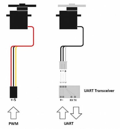
Serial Servos vs. PWM Servos

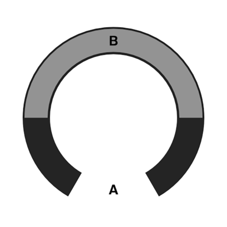
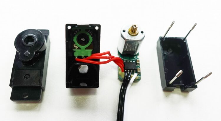
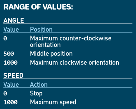
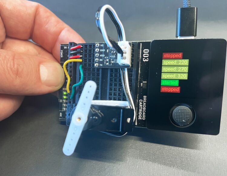
Unlike conventional servos, smart servos can control larger angle ranges and can also be operated continuously. But that’s not all — they can communicate too. Classic hobby servos receive their target angle as a PWM signal and execute the movement, but can’t provide any feedback; whether they actually achieved their desired angle remains uncertain. The smart servo includes a position encoder (magnetic, optical, or a simple potentiometer) and its serial communication is bidirectional — meaning telemetry data can be transmitted in both directions. Besides reading the servo’s position/angle, we can also read values such as input current, temperature, and holding torque.

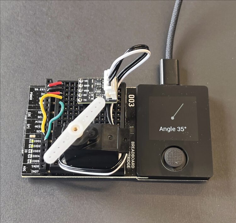
Since the smart servo’s current position can be queried directly, independent of a control loop, it can also be used as an angle measuring device. In robotics, for example, a robot arm can be moved manually into specific positions while the control system records and stores all the servos’ respective angles — in this way, movement sequences can be intuitively “taught.”

Holding torque also provides useful information: it indicates whether the servo is currently under load. If the system detects an unexpected blockage, this can indicate a malfunction. This principle is used, for example, in 3D printers, for detecting the end stop on a linear guide.

Serial servos can be connected to each other via a common bus system. The microcontroller needs only two pins to theoretically control up to 253 servos.
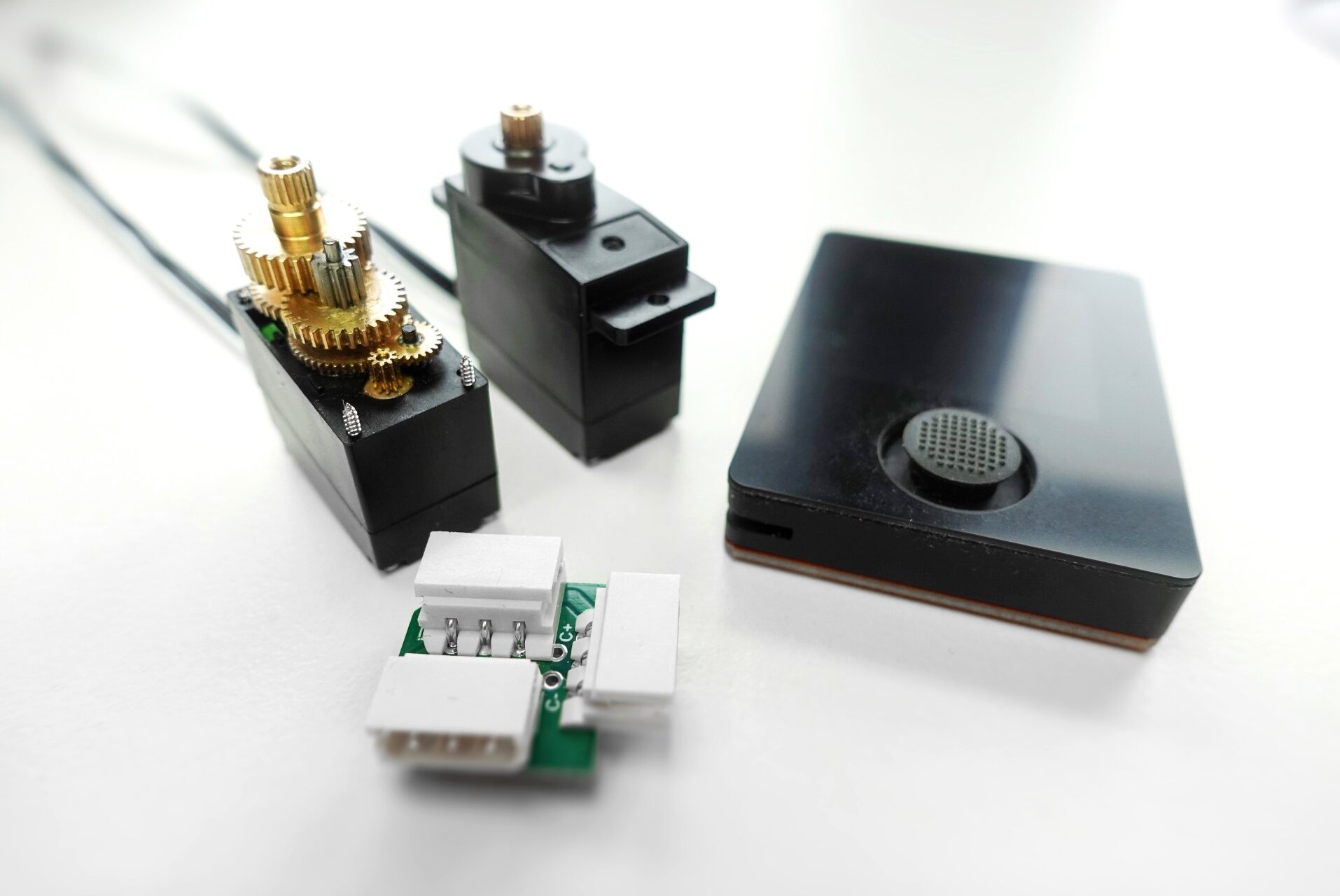
Photography by Thomas Garaio.

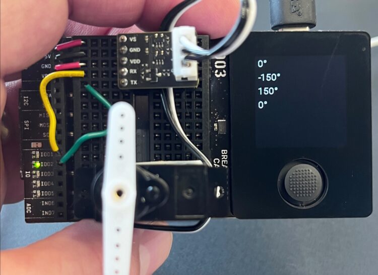
The servo we use here comes from the Chinese manufacturer Feetech, which offers models in different sizes and performance classes. Our model, Feetech SCS0009, is particularly compact and very affordable for hobby projects at just $9. It achieves a holding torque of 2.3kg, with an adjustable rotation range of up to 300 degrees — significantly more than classic analog servos. And our digital servo offers not only the integrated sensor functions we’ve mentioned, but also extensive configuration options — for example, for continuous rotation.

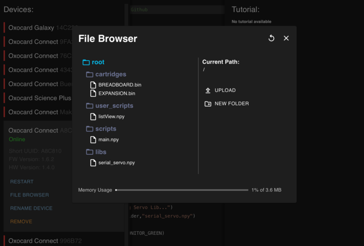
For a long time, serial servo control was considered technically demanding, but that has changed. Today, just a few lines of code are enough to get started right away. In this article, we’ll show you how it works.

Project Steps

1. Set up the Hardware

Communication with this serial servo takes place via the 1-Wire protocol. 1-Wire is what’s known as a half-duplex protocol, meaning that read access and write access both use the same data line.

For this method to work with our Oxocard microcontroller, we’ll use a UART transceiver that splits the 1-Wire signal back into two separate lines: RX and TX.

PWM and UART: same number of pins, but different protocols.

UART stands for Universal Asynchronous Receiver-Transmitter, a widely used serial communication protocol that requires only a few data lines.

This UART transceiver handles the conversion between single-wire and two-wire communication.

The following table shows how the transceiver board is connected to the I/O pins of the Breadboard Cartridge.

To keep the servomotor stable during our experimentation, we attach it to the breadboard with some double-sided tape. This photo shows the final test setup:

After assembly, we attach one of the servo horns to make it easier to observe movements.

CAUTION: Before inserting the cartridge into the Oxocard Connect, check all connections carefully. The 5V power supply is particularly critical. A short circuit with the I/O pins can irreparably damage the Oxocard!

Now that everything is wired correctly, let’s switch from the electronics to the software.

2. Set up the Software

The smart servo is controlled via a special library. To set it up, use the “Install Servo Library” script from the project examples in the NanoPy editor at editor.nanopy.io. (You can also choose Arduino/C++ or CircuitPython to program your Oxocard, but here we’ll stick to the native NanoPy environment.) The required file serial_servo.npy is automatically copied to the libs folder on the Oxocard.

Installation only takes a few seconds — then the library is ready to use.

This library is open source and can also be downloaded directly from GitHub. Custom extensions or corrections can be submitted on GitHub, for example via a pull request — a change request that’s reviewed by the project team and adopted if suitable.

Then you can use the integrated file browser to check whether the file was transferred correctly. Alternatively, files can also be manually uploaded or downloaded from the device back to the PC.

NanoPy’s integrated file browser lets you manage libraries.

3. Explore the Extended Range of Motion

Now you can use the example script “Range Test” to explore the servo’s entire 300° range of motion. The joystick direction determines the movement: move it left, right, and up to move the servo horn accordingly.

The joystick demonstrates the smart servo’s impressive range of motion, by moving left, right, and up.

To begin with, align the servo horn vertically at 0° — this will make orientation easier during later tests.

This servo’s integrated potentiometer, which serves as an angle sensor, has a so-called “dead zone,” so a complete 360° rotation is not possible.

Admire the smart servo’s 300° range of motion (A) versus 180° for a typical hobby servo (B).

Still, where conventional hobby servos usually only achieve 90° to 180°, our smart servo achieves around 300° — a clear advantage for many robotics applications.

A disassembled smart servo. The potentiometer for position feedback, which is connected to the control board via red wires, is clearly visible.

For use in robotics, one technical detail is particularly interesting. PWM-controlled servos have an active internal control loop. Anyone familiar with R/C model making will recognize this behavior: As soon as the power is switched on, all servos automatically align themselves to a defined neutral position and hold it until a control command is received. In more complex robotics systems, however, this behavior can be disruptive — for example, if several robot servos align themselves abruptly at the same time.

The serial servo used here behaves differently: After being switched on, it initially waits for commands. The control system allows each servo to be selectively activated or deactivated as needed.

Code example: Range Test

Line   Code
1    import serial_servo, monitor
2
3    servoBus: SerialServoBus
4
5    servoBus.init(C_PIN_02, C_PIN_01, 1000000)
6    monitor.push("0°")
7        servoBus.setPosition(1,500,1000)
8
9        def onClick():
10           btn = getButtons()
11           if btn.up:
12		 monitor.push("0°")
13		 servoBus.setPosition (1,500,1000)
14           elif btn.left:
15		 monitor.push("-150°")
16		 servoBus.setPosition (1,0,1000)
17           elif btn.right:
18               monitor.push("150°")
19               servoBussetPosition (1,1000,1000)
20           elif btn.middle:	
21               servoBus.stopServo(1)
22               exit()

Explanation of the code

  • Line 1: Import the required libraries for controlling the servo and for output on the Oxocard display.
  • Lines 3–5: To initialize the servo bus, we declare a variable and call the init() function. Here we specify the pins to which the UART transceiver is connected: TX is on C_PIN_02, RX on C_PIN_01. The third parameter sets the bus speed, in this case 1000000 (1 million) baud.
  • Lines 6–7, 12–13, 15–16, and 18–19: In each pair, the first line displays a message on the screen (the text in quotation marks). The second line sends a movement command to the servo, with three parameters: the servo ID number (here 1), target angle, and speed. Since we only have one servo connected, it has the ID 1 by default. Angle and speed are both scalable within a range of 0 to 1,000.
  • Lines 9–22: The onClick() function is called by the operating system as soon as a joystick button is pressed. Line 10 checks which button was pressed. The program then reacts by updating the display and positioning the servo to the corresponding angle.

4. Measure Angles

Here the servo horn acts as an input device: when it is rotated, the measured angle is displayed on the screen.

Now let’s look at the telemetry. Since the serial interface and the servo operate bidirectionally, various measured values can be continuously read out.

In this exercise, we first move the servo to the center position and then deactivate the control. This allows the servo horn to be moved manually. The servo now acts as a sensor: The integrated potentiometer provides a numerical value between 0 and 1,000 over a rotation range of approximately 300 degrees.

The servo has no fixed end stops — the servo horn can rotate a full 360 degrees. However, this potentiometer has a “blind spot” of approximately 50 to 60 degrees, where the potentiometer does not provide stable values, or jumps abruptly from the lower to the upper end of the measuring range. Within this gap the pot cannot be reliably used for angle measurement.

The “Read Angle” script begins, as before, by initializing and centering the servo. The drive is then deactivated, and the current position is read every 100ms.

Code example: Read Angle

Line   Code
1    import serial_servo
2
3    servoBus: SerialServoBus
4    servoBus.init(C_PIN_02, C_PIN_01, 1000000)
5    servoBus.setPosition(1,500,1000)
6    delay(1000)
7    servoBus.stopServo(1)
8
9    setInterval(100)
10
11   def onTimer():
12       a = servoBus.getPosition(1)
13       range300rad = 2.0*PI*0.821
14       range300deg = deg(range300rad)
15       ang = map(a,0,1000,0,range300 rad)
16       push()
17       translate(120,120)
18       clear()
19       fill(150,150,150)
20       drawCircle(0,0,8)
21       rotate(ang-(range300rad*0.5))
22       drawRectangle(-2,-100,4,100)
23       pop()
24       textFont(FONT_ROBOTO_32)
25       setPrecision(0)
26       drawTextCentered(120, 180, (deg(map(a,0,1000,0,range300rad)) - range300deg/2) + "°")
27       update()

Explanation of the code

  • Lines 1–6: Initialize the servo library and position the servo in the center position.
  • Line 7: Deactivate the motor — the servo horn can now be moved manually (with slight resistance).
  • Lines 9–11: After each call to onTimer(), the current position of the server will be read. Line 9 sets an interval of 100ms (1/10 second) between calls.
  • Lines 11–15: After each call, the current position is read on line 12. This is a value between 0 and 1,000, which we convert into an angle on lines 13–15.
  • Lines 16–27: The drawing routine sets the origin to the center of the screen (translate) and rotates the drawing area around this point according to the calculated angle. Then a narrow pointer is drawn as a rectangle.

NOTE: The graphics commands used here are explained in the introductory course that’s built into the NanoPy IDE, under Examples / Getting Started / Basics.

5. Use the Servo as a Motor

The joystick can be used to adjust both the direction of rotation and the speed.

As mentioned previously, this servo can also be used as a continuously rotating drive motor. In this operating mode, a rotational speed is specified instead of a target angle — the servo then rotates freely in either direction.

Controlling an electric motor with a microcontroller usually requires additional hardware, such as a motor driver that processes the digital signal and then provides sufficient voltage and current accordingly. In the smart servo used here, this function is already built in, so the speed and direction of rotation can be controlled directly via software with no need for a separate driver circuit.

To build a vehicle with two drive units, you’d typically need two motors and two controllers. Instead, you could use just two smart servos, reducing costs and simplifying your design. And thanks to their integrated sensors, you can even get feedback to synchronize both drives in case of deviations, for example. The basic servo used here may not be precise enough for this purpose, but advanced models with magnetic encoders and up to 25kg holding torque are available for under $25 and use the same communication protocol.

The motor rotation code example here shows how to put the smart servo into motor mode. The joystick controls the direction of rotation and speed. Pressing the middle button turns the drive on or off.

Code example: Motor rotation

Line   Code
1    import serial_servo
2    import monitor
3
4    servoBus: SerialServoBus
5
6    speed = 200
7    stopped = false
8    direction = true
9
10   servoBus.init(C_PIN_02, C_PIN_01, 1000000)
11   servoBus.setMotorSpeed(1, speed, true)
12
13   def onClick():
14      btn = getButtons()
15	
16      if btn.middle:
17          stopped = not stopped
18          if stopped:
19              monitor.pushc("stopped",
MONITOR_RED)
20          else:
21              monitor.pushc("started",
MONITOR_GREEN)
22      elif btn.left:
23          direction = false
24          monitor.push("CCW")
25      elif btn.right:
26          direction = true
27          monitor.push("CW")
28      elif btn.up:
29          speed = bounds(speed+50,0,
1000)
30          monitor.pushc("speed: " + speed,MONITOR_YELLOW)
31      elif btn.down:
32         speed = bounds(speed-10,0, 1000)
33         monitor.pushc("speed: " + speed,MONITOR_YELLOW)
34
35      if stopped:
36          servoBus.stopServo(1)
37      else:
38          servoBus.setMotorSpeed(1, speed, direction)

Explanation of the code

  • Lines 6–8: Three variables are used: speed stores the current speed; stopped is true when the motor is stopped; and direction indicates the direction of rotation (true = clockwise, false = counterclockwise).
  • Line 11: Activates the motor mode for the servo. The function expects three parameters: servo ID number, speed (0 to 1000), and direction of rotation.
  • Lines 13–38: The event function processes key inputs to change the direction of rotation, speed, or on/off status of the motor.
  • Lines 16–21: When the middle button is pressed, the variable stopped toggles between true and false. The current state is then displayed.
  • Lines 22–27: Pressing left or right changes the variable direction — thus switching the direction of rotation.
  • Lines 28–33: The up/down buttons also control the direction, as an alternative control logic.
  • Lines 35-38: Finally, the motor is activated or deactivated depending on the value of the variable stopped: If it’s true, the servo is stopped. If it’s false, the speed and direction are transmitted again via UART.

Conclusion

Arduino and Oxocard!

The Oxocard Connect’s custom NanoPy language has its advantages: it’s fast, runs immediately without reflashing, and helps you learn Python (or leverages your existing Python skills over to microcontrollers).

But at its heart the Oxocard has a familiar ESP32 microcontroller, which means you can use the language of your choice — including C++ in the familiar Arduino environment. It’s easy to set up, following the simple instructions.

Similarly, you can program your Oxocard with CircuitPython, following the instructions. 

And whenever you want to revert to NanoPy, it’s always easy to do using the web installer provided by Oxon. 

More to Learn

• Serial servos are key to robotics and much more. To learn more about using them, check out Kevin McAleer’s overview and demonstration video. 

• Find more fun projects to make with the Oxocard Connect!


This article appeared in Make: Volume 96.