Follow wiring diagram to connect the electronics. See the program and wiring diagram to get the pinout for the Arduino.
Connect motors to the drivers – this wiring depends on the motors and drivers you select. If you use the ones we did, its a quick connect with a Molex connector.
Connect drivers to the Arduino. Most motor drivers have a direction, pulse and common ground wires or CW pulse, CCW pulse and ground. These are the ones you are mostly concerned about. Some have “all windings off” and other options.
Connect one of the solenoid of the leads to the power supply.
Connect the relay DC control to the Arduino pin and the common ground. If it’s a solid state relay, be sure to connect it in the right direction, or it won’t switch. Connect the Normally Open (NO) lead to the power supply and the other side to the solenoid.
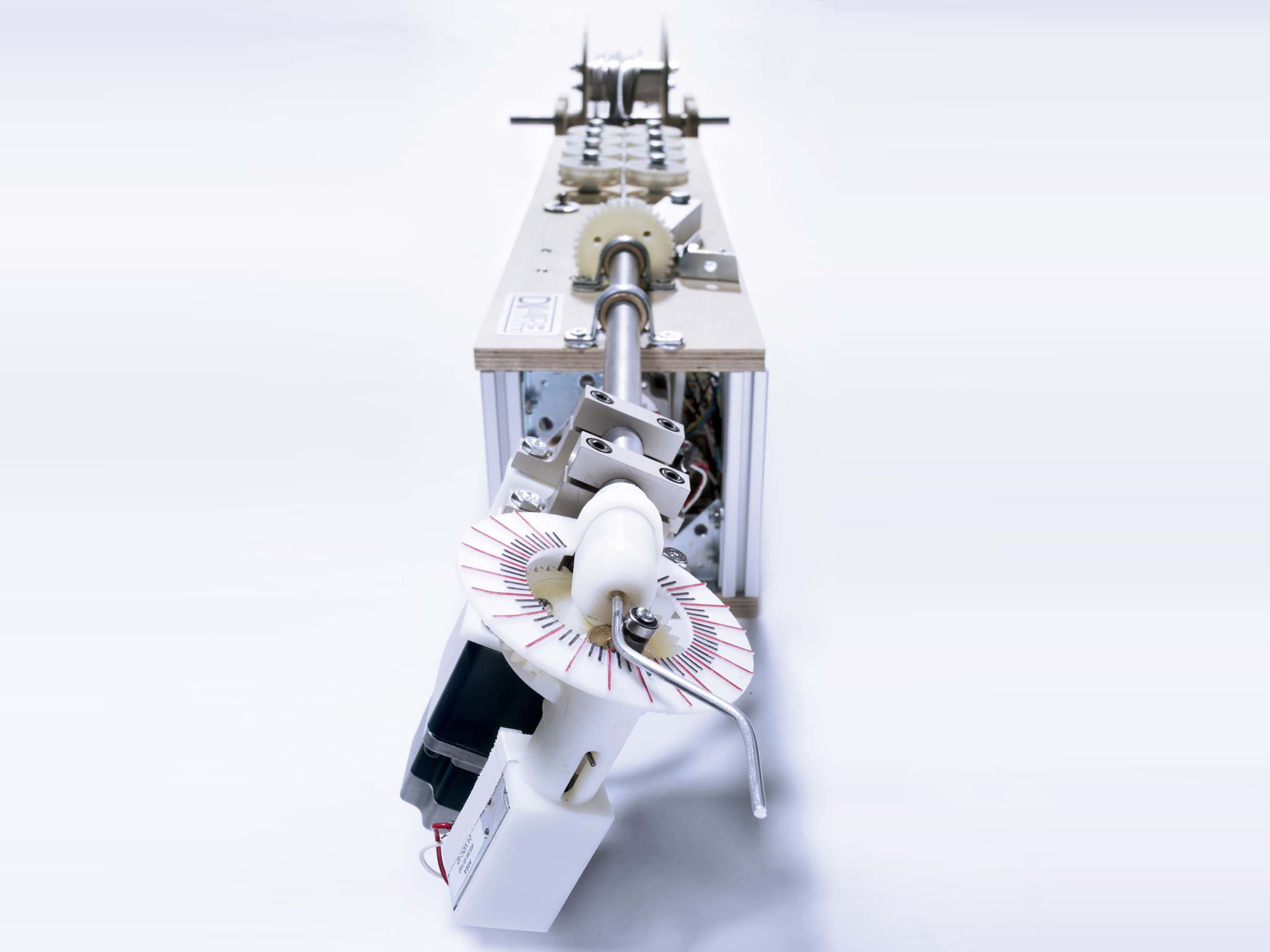
Put the steel gear on the bender motor, and the knurled knob on the feeder motor. Don’t put the nylon gear on the Z-bend motor yet.
Before the next step, test the Arduino and Processing programs to make sure the gears turn and the solenoid moves as expected.


