


If you’ve ever wished you could program your Arduino without lugging a USB cable around, wanted to put an Arduino project somewhere out-of-reach but still be able to easily upload changes to it, thought about building a project that interfaces with an Android phone, or contemplated a way to get remote sensor data streamed to your computer — this project is for you.
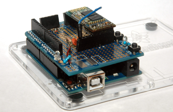
It uses a common, low-cost Bluetooth module mounted onto a prototyping shield for durable and reliable use. Along with the module is a circuit that allows the Arduino IDE to automatically reset the Arduino when uploading a new sketch. This project also uses the latest version of the Arduino IDE which eliminates the need to hack in modified DLL files to get the serial programming to work.
Besides uploading sketches, the shield can be used for serial communication using the standard Arduino Serial library between multiple Arduinos, smartphones, computers, or even a Bluetooth-enabled Raspberry Pi.
You will need a computer with built-in Bluetooth or a USB Bluetooth dongle to use the shield to upload sketches to your Arduino. These instructions are specific to Windows 7, but should be similar for Windows 8. Mac and Linux users can probably figure out how to get this working too. Smartphones need to support Serial Port Profile (SPP) to work (this excludes iPhones but includes many Android phones). This project is moderate to difficult, and requires soldering and previous prototyping experience.


