

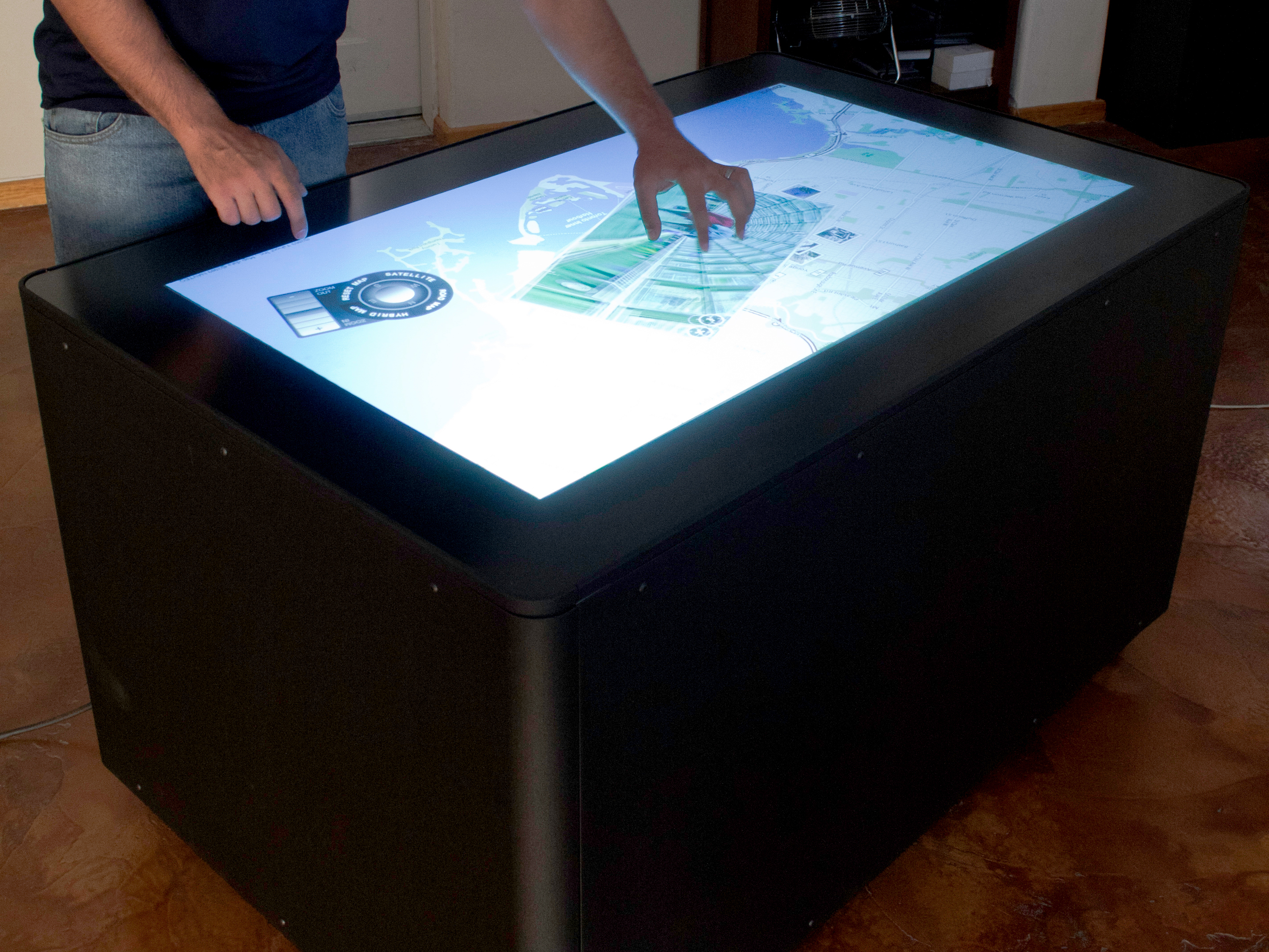
The MT50 is a projection based 50” multitouch table. It is 31” high with casters and meets ADA (American’s with Disabilities Act) standards. The MT50 supports a resolution of 1280×720. Its frame is made of aluminum, the shell is steel, and surface is thick tempered glass. The table is virtually indestructible and is designed for use in busy public spaces.
We’ve literally dropped bowling balls on it to test its toughness.
The MT50 is a projection based 50” multitouch table. It is 31” high with casters and meets ADA (American’s with Disabilities Act) standards. The MT50 supports a resolution of 1280×720. Its frame is made of aluminum, the shell is steel, and surface is thick tempered glass. The table is virtually indestructible and is designed for use in busy public spaces.
Ideum, a New Mexico-based company, built and sold MT50 multitouch tables between 2009 and 2010. There are dozens of these tables installed in museums, research labs, and a few are even installed at Fortune 500 companies across North America.
The MT50 has been discontinued, as of March 2011, and has been replaced by a LCD based table, the MT55 HD.
It is worth mentioning that many of the techniques used in the MT50 are still used for large-scale installations such as walls and multiple projector tables. While the MT50 documentation is no longer available on the Ideum site. A description, videos, and reviews can be found on the GestureWorks website.
The instructions for the MT-50 are being released as part of the Open Exhibits, museum software and hardware initiative. Open Exhibits multitouch and multiuser software is free to students, museums, nonprofits, and US Government agencies.
If you have any suggestions for how we might improve these instructions, please let us know.
The Ideum and Open Exhibits Team
Corrales, New Mexico