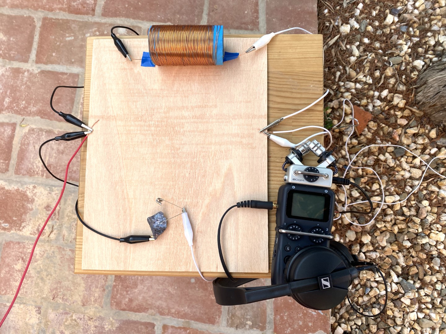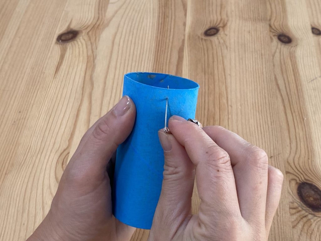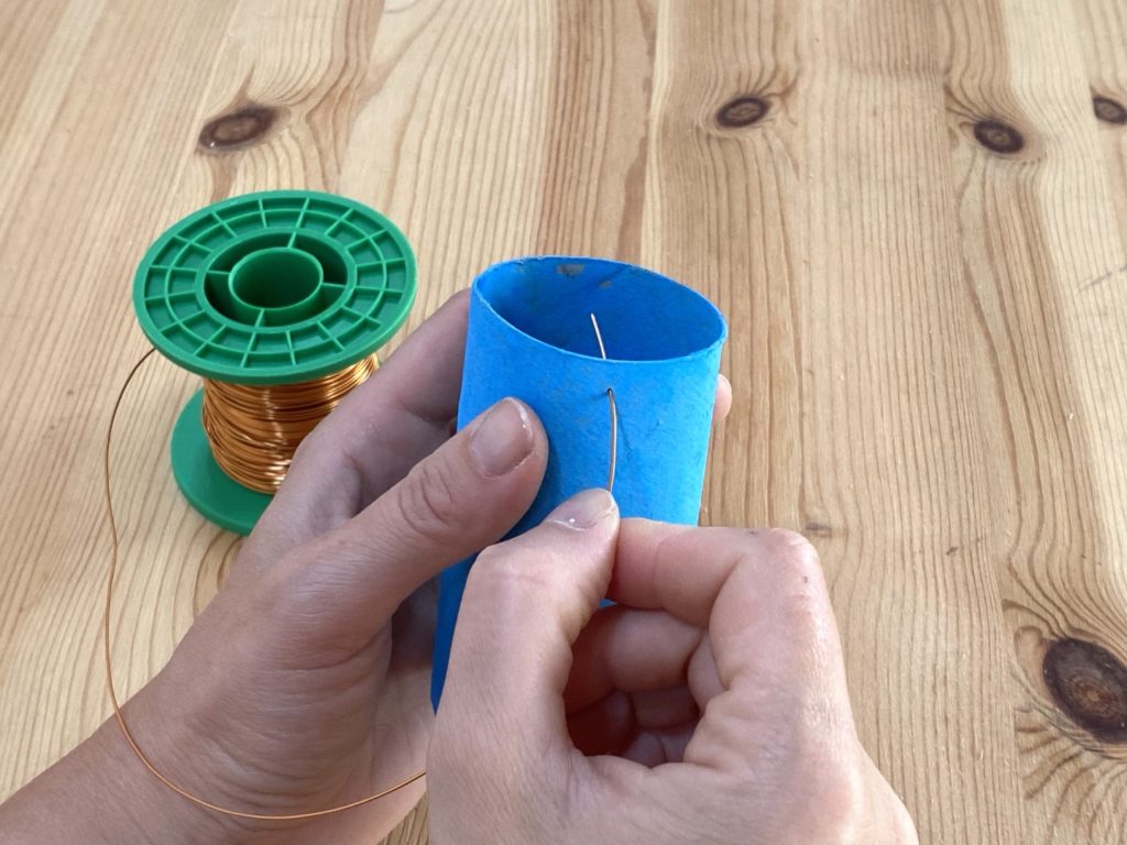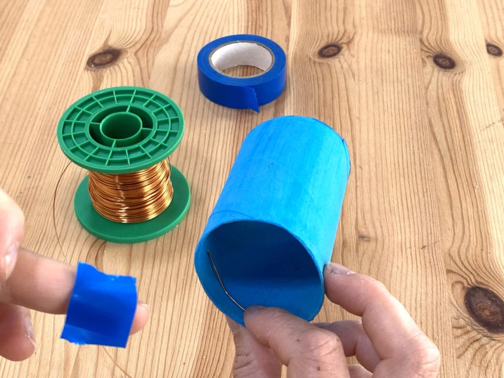
Shortwave Collective is a 10-member feminist art group founded in 2020. Collectively, we’ve been exploring the process of radio circuit assembly, considering the radio spectrum as an artistic material, and building self-powered radio receivers. Through an artist residency at Buinho Creative Hub in Portugal, we also spent a week of in-person and remote collaboration developing radio wave receivers and experimenting with designs with others in an open workshop.
Here are some of the lessons we’ve learned — and how to build your own radio wave receiver.
A FEMINIST APPROACH TO BUILDING RADIO
We support inclusive and participatory STEM education that transcends gendered stereotypes. We learn by collaboratively doing, with a goal of exploring creative possibilities. We believe in demystifying technologies and connecting with others by making and doing.

With our experimental radio projects we are interested in listening, in a broader sense. We measure success in ways other than by signal strength or tuning frequencies for the clearest sound. Instead, we are interested in all the sounds detected — data signals, talk radio, and sferics (radio bursts emitted by lightning) alike. We are fascinated by the idea that radio waves surround us, and being able to detect them and translate them into audio signals to listen to illuminates something about our environment.


What interests us about the radio wave receiver projects is their accessibility. It’s a great way to learn about the physics of radio through practical experimentation.
SIMPLE RADIO CIRCUITS AND OPEN WAVE-RECEIVERS
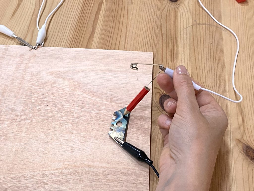
Probably the most famous example of simple radio design in action is the foxhole radio. These were made from materials that were accessible to soldiers in the trenches (foxholes) during World War II. Though designs varied, they typically used a razor blade, pencil, and safety pin for parts. The official military vacuum-tube radios used during the war could be traced to reveal broadcast or reception locations, but foxhole radios operate without a power supply, and could not be detected. Thus, soldiers used them as a way to safely keep up with the world from their posts.
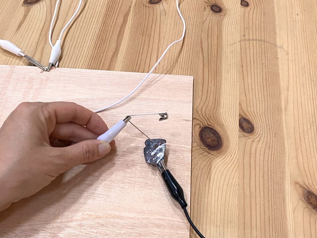
Crystal sets are another form of early radio circuitry — a popular DIY project in the 1920s and even today — that relies on a mineral crystal (usually galena) as a radio wave detector.

WARNING: If you’re listening through headphones, be mindful that volume increases can be unpredictable. To avoid damaging your hearing, make sure you have a complete circuit with both diode elements touching before you put your headphones on, and take them off before these pieces are disconnected.
We began our experiments by examining popular designs for radio receivers, such as crystal sets and foxhole radios. There is a basic recipe to build simple radio circuits, and we found many how-to examples and diagrams on websites, YouTube, and in books. Soon we found ourselves more fascinated with the process and experimentation, rather than the end product of replicating others’ radio visions. Hence we refer to our project (and variations of it) as making an Open Wave-Receiver.
The fun of building an Open Wave-Receiver is in exploration and experimentation to find materials and environmental conditions with strong enough signal to receive radio waves. These radio constructions can be simple or souped-up, depending upon how the found materials vary the aesthetic or the elements of the circuit.
EXPERIMENTAL MATERIALS: FOUND, FENCES, AND TENT PEGS
Building Open Wave-Receivers enables DIY communications reception, and allows anyone to freely listen to the broad spectrum of radio waves around us. All you need are a few easy-to-procure supplies and, if you want to try it, a neighborhood fence or other receptive antenna proxy.
Why a fence? Antennas are necessary for radios to receive signals, and many things can be antennas. Fences can make great, and very long, antennas! Other materials can work well too; even a tent peg can become a useful part of a radio. Open Wave-Receivers allow us to explore the relationship between different combinations of materials, antennas, and radio waves, creating a new technology literacy, a new medium for artistic expression, and a new way to explore the airwaves in our communities.
We have found making Open Wave-Receivers to be a fun adventure. The ability to use simple scraps to create variety and personalization in each radio makes this a great maker project for anyone wanting to play with radio.
BUILD YOUR OPEN WAVE-RECEIVER
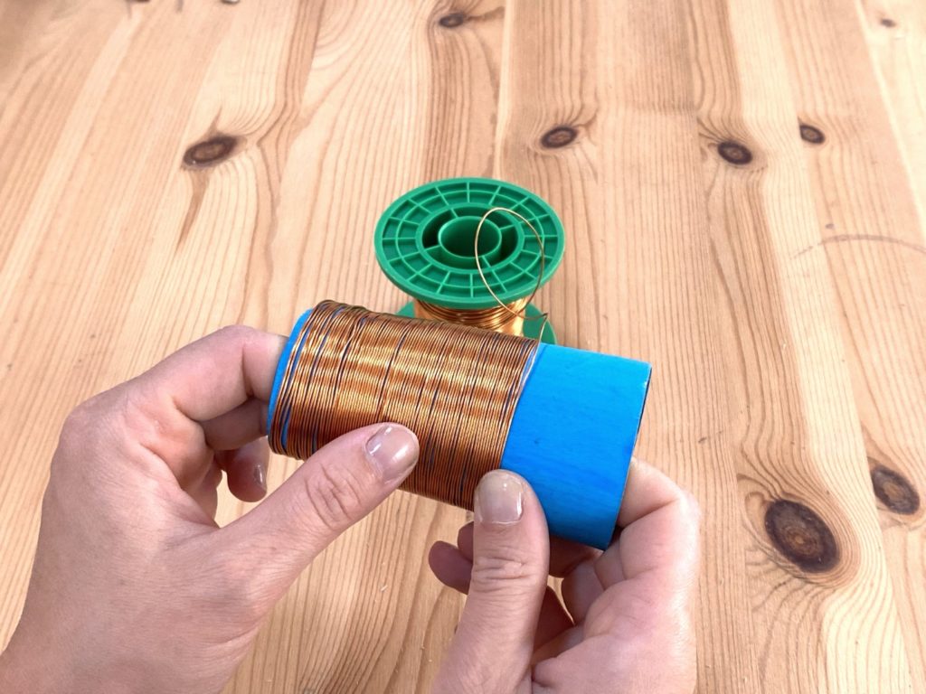
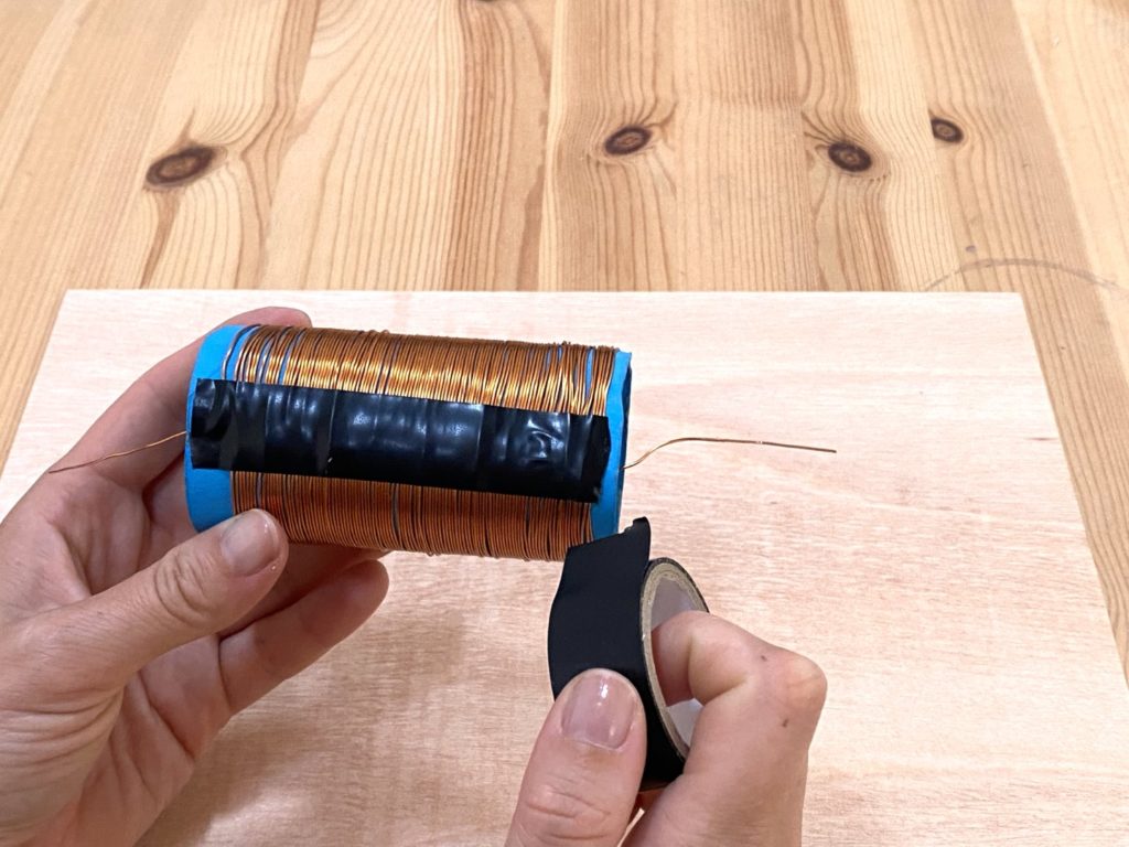
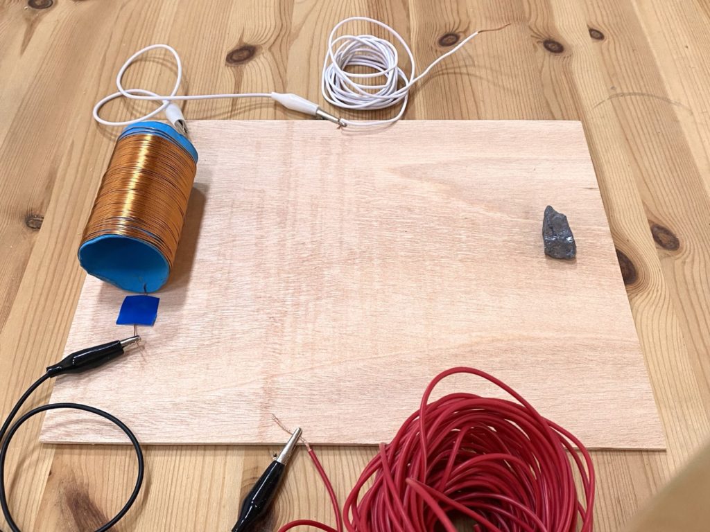
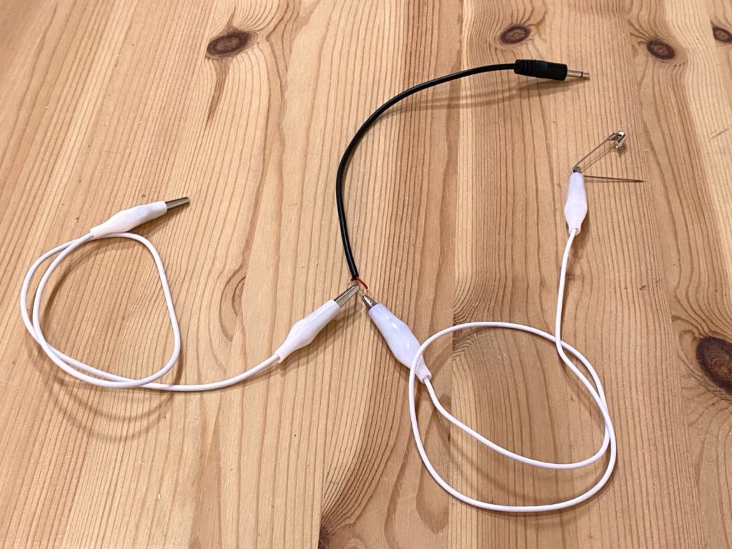
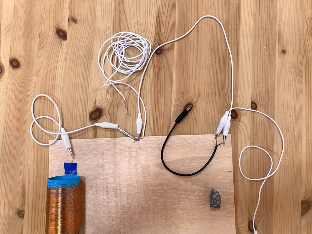
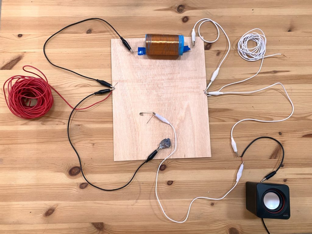
Let’s get building! Here’s how to make an Open Wave-Receiver from readily available materials. Building it will enable you to listen to airwaves and to reveal the invisible sounds that surround you — transmitted near and far — while becoming aware of how environmental and atmospheric conditions affect radio reception.
LISTENING
Your radio is not just location specific, but time,
weather, and season specific! We’ve found signals to be strongest during “grey line” time — dawn and dusk. Dry conditions will also help.
We haven’t included a tuning arm in this build — it’s really part of our ethos to listen to the environment as we find it rather than look for a clean signal. (Foxhole designs with a tuning arm are well documented on the internet.) Though signal strength is important so you can test if your radio receiver is working, we feel it is just as exciting to listen to radio that is quiet, perhaps sounds out with strange beeps and hums, or has multiple stations competing rather than one clear signal. We are making audible the invisible radio waves around us and listening to them as they interact with our environment, rather than aiming to filter them to a predetermined mode.
EXPERIMENT!
• Try throwing your antenna up in the air, and hear how the volume increases as it flies.
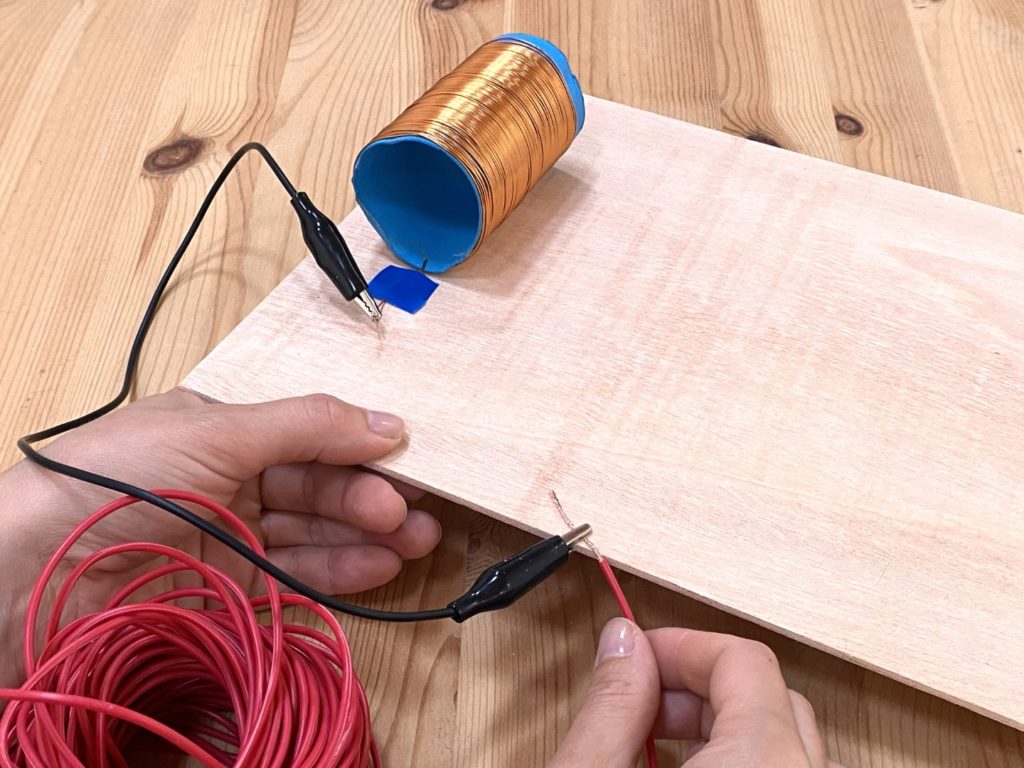
• Is there a metal wire fence nearby that you could use as an extra long antenna (e.g., a fencetenna)? Clamp it with a crocodile clip.
• Try making a new coil by wrapping another length of enameled wire around a found object.
• See what metal objects you can swap your diode for to detect your signal.
Our experiments, and those by participants in our workshop at Buinho Creative Hub, Portugal, include:

• A rock at the center of the coil, altering its air-core properties (Carlos Alcobia) (Figure P )

• Cork bark local to the area as a base-board (Anaïs Schendekehl) (Figure Q )

• A wearable radio in the shape of a hat, made from scrap material (Brigitte Hart) (Figure R )
• Tent-peg diode radio — replacing the razor/crystal and “cat’s whisker” diode (Hart, Lisa Hall, and Hannah Kemp-Welch)
• Found-object diode radio (Hart, Hall, and Kemp-Welch)

• Roof radio — coil wrapped around a roof tile (Hart, Hall, and Kemp-Welch) (Figure S )

• Multiple diode design, with numerous rusty and blued razors built in (Georgia Muenster) (Figure T )

• Basket-weave coil for a crystal radio, work in progress (Kate Donovan) (Figure U )
• The Fencetenna project was a selection of radio receivers including foxhole, crystal, and shortwave receivers that were connected to fences as antennas, implemented by Shortwave Collective members Alyssa Moxley, Brigitte Hart, Georgia Muenster, Hannah Kemp-Welch, Lisa Hall, and Sasha Engelmann. Behind-the-scenes support came from members Sally Applin and Franchesca Casauay, with thanks to Soundcamp 2021 for inviting us to their event program.
HOW DOES IT WORK?

• The antenna picks up radio waves from all directions. Radio waves flow through the metal, creating an electric field, which moves along the length of the aerial to produce an alternating current.
• The coil exchanges current with the antenna. It stores the current and smooths it as it runs through the circuit.
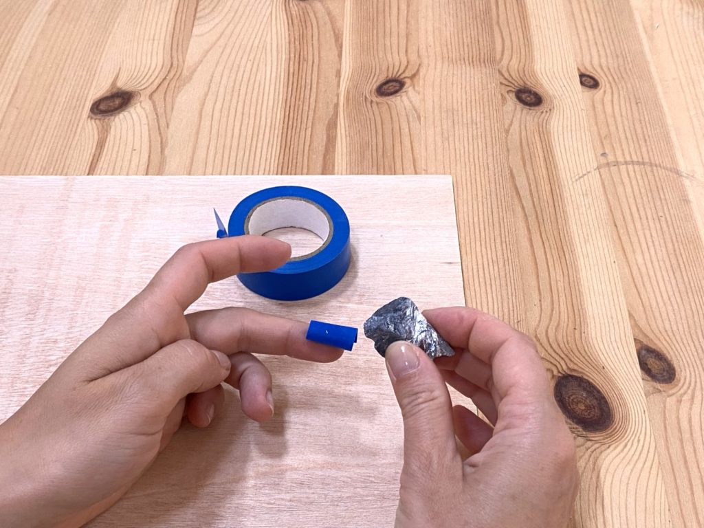
• Diodes have two parts: a crystal or razor blade and a “cat’s whisker.” When the two parts meet they act as a gate or semiconductor, only allowing current to flow in one direction. They strip the radio wave, leaving only an electrical signal.
• The phones convert the electrical signal into sound.
• The ground allows the current collected through the antenna to dissipate and leave the circuit.


