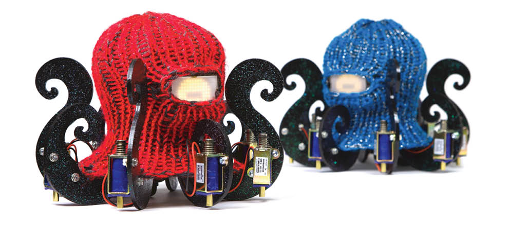
Have you ever wanted your own cute and friendly robot that you can play music with? Dr. Squiggles is just that — a musical drumming robot that plays rhythms by tapping on whatever surface you set it on. Moreover, if you tap rhythms, it can listen to you through its microphone, synchronize to your beat, imitate you, or learn to play rhythms that are similar but not identical to yours!

YouTube player

When I designed Dr. Squiggles, I wanted to make the most mechanically simple robot I could think of, and try to imbue it with the most complex behavior possible. Essentially, it’s just a contact microphone and eight solenoids controlled by an embedded computer.

A functional block diagram of Dr. Squiggles

• Eight solenoids tap the rhythms.

• A low-res LED matrix serves as the robot’s eye.

• A contact microphone listens selectively to rhythms that you play.

• An embedded Raspberry Pi computer does the “smart” tasks of analyzing what you play and generating rhythms.

• A Teensy microcontroller animates the eye and receives USB-MIDI messages from the Raspberry Pi, upon which it applies voltage to the solenoids, causing them to eject and make tapping sounds.

this project is from the latest issue of Make: Magazine. Get yours now!

I designed Dr. Squiggles as part of my research at University of Oslo, where I study human-robot and robot-robot interaction in the context of music. Recently I’ve been especially interested in how swarms of simple robots can make music together, so my colleagues and I built ten Dr. Squiggleses. We got really good at building them and so we wanted to share the process with you!

Project Steps

CUT AND PAINT PLYWOOD PARTS

plywood parts for Dr. Squiggles’ body. Download the OpenSquiggles repository, then open the design file OpenSquiggles/Hardware/Laser.pdf in your laser cutter’s software, such as CorelDRAW or FlexiDesigner.

For now, you can delete the two parts on the far right that are labeled “paper” and “2mm acrylic” (you’ll cut those out later). Select all the remaining paths and set the line width to “Hairline” or “0mm” as required by your software, to indicate they should be cut as vectors.

Cut the parts on the laser. They can be cut from a single 300×400mm sheet of plywood, but plan on using two to account for mistakes. I used a 30-watt Epilog Zing with the following settings: Speed 18%, Power 100%, Frequency 500Hz.
If some parts are stuck, you might need to gently score the back of the plywood with a knife to release them.

Painting the tentacles

Identify the 7 curly tentacle pieces labeled 3, 5, 7, 8, and 9. Lightly sand them, being careful not to break them as they’re quite fragile at the thinnest places.

Paint the parts of the tentacle that will be visible in your final robot . I put one coat of black furniture paint, and let it dry overnight. Then I sprayed clear acrylic varnish on the parts and sprinkled in some glitter while it was still wet. I let that dry for a couple hours, then sprayed a second coat of acrylic to seal the glitter in place. It would be cool to try different color schemes. Be sure to paint both sides of the plywood.

PROGRAM THE TEENSY

Start by installing the Teensyduino software on your laptop or PC. Then replace one of Teensyduino’s native files with a file from the OpenSquiggles repository. The file you’re replacing is called usb_desc.h. On OSX, it’s found in /Applications/Arduino.app/Contents/Java/hardware/teensy/avr/cores/teensy3/usb_desc.h. Replace it with the file found in the OpenSquiggles repository at OpenSquiggles/Firmware/Teensy_Replacements/usb_desc.h. This will make the Teensy enumerate as a USB MIDI device called Dr Squiggles and not Teensy MIDI, so that the OpenSquiggles main software will talk to it properly.

Now find Dr. Squiggles’ firmware in the repository at OpenSquiggles/Firmware/Firmware.ino, and open it using the Teensyduino software. From the main menu, select Tools → Board → Teensy3.2 / 3.1, and then Tools → USB Type → MIDI. Connect your computer to the Teensy via USB. Press the Upload button in Teensyduino to program the Teensy, then disconnect the Teensy from your computer.

CUT THE TEENSY VIN TO VUSB TRACE

Use a needle or small blade to sever the tiny trace on the bottom of the Teensy that connects USB power to the rest of the board. After you’ve severed it, you can use a multimeter to check that there is no longer continuity between the two pads.

This makes it safe to power the board with an external power supply, but it means the board can no longer be powered via USB. To be reprogrammed it will need an external power supply, which won’t be added until Step 9.

ASSEMBLE THE MAIN CONTROLLER BOARD

The main controller circuit controls Dr. Squiggles’ solenoids and eye, and supplies power to the Raspberry Pi. This module has two variants.

• PCB version: Download the PCB design file OpenSquiggles/Hardware/Board.zip and have it manufactured at a PCB house. Or order PCBs direct from OSH Park (3 board minimum).

Solder header pins to the Teensy and the voltage regulator. Then solder the Teensy, regulator, Darlington driver, terminal block, and remaining headers to the PCB.

• Perf board version: Use a hacksaw to cut a piece of generic perf board 13 holes wide and 23 holes tall. Solder header pins to the Teensy and the voltage regulator. Tack-solder the parts as shown above , and then connect them by bridging adjacent pads on the bottom of the board with solder. The right-hand side of the image above shows the finished board with the trace locations drawn over the top (component-side) of the board, and the component locations drawn over the bottom (solder-side) of the board, which will help you during assembly.

SOLDER THE LED MATRIX TO ITS DRIVER

Now you’ll prepare the electronics for Dr. Squiggles’ eye module. Solder a 7-pin header to the top of the LED driver board (IS31FL3731). Then use two 13-pin headers to solder the LED driver back-to-back to the LED matrix. The LED matrix has rotational symmetry, so it doesn’t matter which way you install it, as long as the LEDs are facing out. Adafruit has a detailed assembly guide.

MAKE THE EYE MODULE

e laser-cutter design file again, OpenSquiggles/Hardware/Laser.pdf. This time you’ll cut the part labeled “paper” out of regular printer paper and the “2mm acrylic” part out of a sheet of clear, 2mm thick acrylic. Delete the text from these parts in the file, and make sure the stroke width is set to zero or hairline.

Then cut the parts one at a time out of their respective materials. If the acrylic has a plastic backing, cut it with the backing side down, and remove the backing after the part has been cut. These parts will diffuse the light from the LED matrix. I used the following settings on the 30-watt Epilog.

For the acrylic: Speed 40%, Power 100%, and Frequency 5000Hz.

For the paper: Speed 100%, Power 12%, Frequency 500Hz.

Glue the four plywood pieces labeled 11 and 12 (two of each) into a rectangle. Next, mix up a small amount of epoxy, put a drop on each of the four tabs on the acrylic panel, and then press the tabs into their slots in the plywood rectangle. Wait for everything to dry.

Drop the paper diffuser into the box so it’s lying on the acrylic. Then drop the LED assembly in so the LEDs are pressed up against the paper. Put a dab of hot glue in one or two of the inside corners, to lightly pin the LED driver board inside so it can’t fall out.

START GLUING THE BODY

Now you’ll start gluing together the plywood parts to form the body of the robot. You will assemble the final circuit into the body as you go. Use liberal amounts of wood glue on all contacting surfaces, and refer to the photos for plywood part numbers.

Insert the Raspberry Pi USB and Ethernet jacks into Part 1, the bottom plate. Clip them in place by gluing Part 2 (Pi clip) to Part 1. Slide the bottom slit of Part 3 (left and right tentacle plate) over Part 1, and glue 3 to 2 and 1, as shown.

Now glue Part 4 (top plate) into the top slit of 3, so its holes extend over the Raspberry Pi SD card slot. Glue Part 5 (rear tentacle) into the rear slots on 4 and 1. Glue Part 6 (rear tentacle upper extension) to 3 and 4.

Glue the two Parts 7 (rear-left and rear-right tentacles) into 3 and 4. Take a break from gluing.

MAKE CONNECTOR CABLES

Start by making the eye module cable. Cut four 7cm lengths of wire and use a Molex crimping tool to attach a female crimp terminal to each end. Then insert the crimped wire ends into plastic 4-position crimp housings. By the same process, make the 2-wire, 12cm Pi power cable.

Also solder two 2cm wires to the on/off toggle switch, and crimp a 2-position terminal to the free ends. Do the same to the pushbutton using a 5cm and 10cm wire. The toggle is Dr. Squiggles’ on/off power switch. The pushbutton is a safe-shutdown button for the Raspberry Pi.

You also need to crimp a 2-position connector to the end of all the solenoids, however, I recommend waiting until after Step 12 so you can trim the solenoid wires to length first. All the completed cables are shown above.

INSTALL THE ELECTRONICS

Use plenty of hot glue to affix the main controller board to Part 3. Mount the toggle and pushbutton in their holes in Part 1 using the nuts and washers that came with them.

If your power supply came with a connector on the end, cut it off and discard it, and strip and tin a few millimeters at the end of the wires. Thread this power cable through its hole in Part 1, put the tinned ends into the screw terminals on the main controller board, and screw them in place. Hot-glue these wires in place to prevent them from being accidentally pulled out later. (The correct polarity of the power cable in the terminal is shown in step 13 below).

Also thread the micro USB cable through its hole in Part 1. Plug it into the Teensy and secure it from below with lots of hot glue, because this USB jack is prone to breaking off irreparably.

FINISH GLUING THE BODY

Glue Part 9 (front tentacle) to 3, then glue Part 10 (front tentacle upper extension) to 4. Finally, slide the two Parts 8 (front-left and front-right tentacles) into 3 and 4, but leave these unglued so the circuitry can be accessed.

DAMPEN THE SOLENOIDS

When voltage is applied to a solenoid, it ejects and, in our case, strikes something, making a sound. Then, a short time later, when the voltage is removed, the solenoid retracts, and the plunger rams into the metal frame of the solenoid, making a second sound. This second sound is undesirable, and in this step you will dampen it.

Cut a small rectangle out of 1mm thick hobby felt. Cut a small hole in the center of the felt, and stretch it over the solenoid plunger. Use gel cyanoacrylate super glue to glue the felt to the frame of the solenoid, so that when the plunger retracts it strikes the felt instead of the metal frame. Do this to all 8 solenoids.

MOUNT THE SOLENOIDS

Screw a solenoid onto each tentacle, using a washer and a nut on the back of each screw. Carefully adjust each solenoid up and down until it just barely strikes the table when fully ejected, and then tighten the nuts.

Thread the solenoid wires through their holes in the bottom plate, Part 3.The four wires from the back of the robot can be threaded between the back of the Raspberry Pi and the tentacles, and then passed to the front of the robot through the small remaining hole in Part 3, just next to the Pi headers. Now you can trim the solenoid wires to length and crimp connectors to the ends, as in Step 8.

WIRE EVERYTHING TOGETHER

Connect all the circuit components using the cables you made in Step 8, following the wiring diagram. Of course you’ll connect all these components in place inside the body, not out in the open as shown.

GLUE THE EYE MODULE TO THE BODY

THE EYE MODULE TO THE BODY

You’ve already connected the eye module to the main controller board. Now glue it to Parts 9 and 10 (front tentacle lower and upper parts). Make sure the row of header pins that connect the eye to the controller are on your left when you’re face to face with the robot, otherwise the eye will be upside down.

KNIT A BALACLAVA HAT (OPTIONAL)

In this module, you will knit a balaclava hat for Dr. Squiggles to wear. You can also just buy a balaclava for him. I used an Addi Express king size circular knitting machine, although a skilled knitter could do this by hand. I recommend using either a chunky weight yarn, or two pieces of DK weight yarn simultaneously. This will make it difficult to operate the machine, but the final product will be thick and opaque, fully hiding the robot’s internal components while keeping it nice and cozy.

First you’ll knit a flat panel that’s 25 columns wide by 40 rows tall, with a 6-column hole in the middle of it. Then you’ll stitch together the edges of the panel to form a cylinder with a circumference of 24 columns, and cinch off the top to form a balaclava.

Prepare the machine by putting the operating switch up into the plain knitting position. Place a stopper between pins 32 and 33. Cast on with the working yarn (green) by catching it under the even-numbered pins from 4 to 28 inclusive as shown below at left. Do not let the yarn catch on pins 29 or 30. Then knit 20 rows, not counting the cast-on pass as a numbered row. You will be knitting on pins 4 to 28 and even-numbered rows end at pin 28, as shown at right. More information is in the Addi instruction manual (PDF).

You now need to knit an eye hole into row 21. Start knitting the 21st row normally from pin 28, but stop after the yarn is caught by pin 19. Cut off the working yarn, remove it from the machine, and replace it with waste yarn (orange), as shown below. Knit 6 stitches with the waste yarn, from pin 18 to 13, inclusive. Cut the waste yarn off, and replace it once again with the working yarn, leaving about a 1 meter tail of working yarn which will later be used to bind off the eye hole. Knit the remainder of row 21 starting from pin 12 and finishing on pin 4. Then knit 19 more rows, for a total of 40 rows, as shown.

Cut off the working yarn leaving a tail of about 2.5 meters, which will later be used to finish off the work. Remove the working yarn from the machine and replace it with waste yarn, as shown below. Knit about 6 more rows with waste yarn, as shown. These rows temporarily keep the work piece from unravelling but will be removed later. Cut off the end of the waste yarn leaving a tail of about 60cm, and thread the tail through a yarn needle. Bind the piece off the machine by slowly advancing the machine and passing the needle through from each active stitch as it is released from its pin, as shown.

Crochet the loose ends
Now you’ll finish off the loose ends of the balaclava. First you’ll finish the eye hole with a crochet hook. Place the workpiece in the orientation shown below. At the top of the eye hole, the waste yarn is holding the ends of 6 columns. At the bottom, it is fully holding the ends of 5 columns, plus 2 half-columns at each side. Earlier, you left a 1-meter tail of working yarn in Row 21. Grab it with a crochet hook and pull a loop through the rightmost half-column on the bottom. Bind off the bottom of the eye by making 6 single-crochet stitches: one in each of the 5 exposed column ends, and one in the leftmost half-column end. Chain one and rotate the piece 180°. Then single-crochet into the 6 column-ends in the top of the eye hole. Chain one again. Then tie off the loose end near to where you started crocheting and cut it to a few centimeters in length. Additionally tie off the free end of working yarn on the other side of the eye and cut it to a few centimeters in length. Pull out the waste yarn, and the eye hole will open.

Next, bind off the exposed ends of row 40. Put the workpiece in the orientation shown below. In Step 16 above you left a 2.5 meter tail at the end of row 40. Grab it with a crochet hook and pull a loop through the rightmost stitch of row 40. Chain one. Single-crochet into each column of row 40, and chain one after each single-crochet stitch. This row will eventually stretch around Dr. Squiggles’s tentacles, and without the chain stitches the final circumference will be too small to fit. Take the yarn off the hook and pull the loose end through the loop to secure it against unraveling. Cut the waste yarn (orange) fully off the workpiece and discard it.

Finally you will close up the flat panel to form a hat. Put the workpiece in the orientation shown in above. Take the loose end that you just removed from the crochet hook and thread it onto a yarn needle. You will use this to create a mattress-stitch that joins the two sides of the flat workpiece together to form a cylinder. You will be working one-half column away from either side of the workpiece. On the left, this corresponds to the area that was between pins 4 and 5 when the piece was on the knitting machine, and on the right, pins 27 and 28. These columns are marked with small arrows below. Draw the needle through rows 40 and 39 on the left side, then on the right side. Then through rows 38 and 37 on the left then right. Continue this until you’ve reached the top of the piece, tightening the stitch as you go. Then, set down the tail of yarn you’ve been working with and pick up the other loose end. That is connected to the original cast-on row below. Cinch together the top of the balaclava by carefully pulling on it, as shown. Then, tie the two loose pieces of yarn together and tuck them inside the hat.

PROGRAM THE RASPBERRY PI SD CARD

The Raspberry Pi OS (formerly Raspbian) requires a good amount of configuration to work in Dr. Squiggles, so to simplify installation, I’ve made a disk image that contains the fully configured operating system. Download it onto your computer and unzip it. Copy the disk image onto a 16GB microSD card, using the following tutorial for MacOS, or whatever works for your computer.

Once you’re done, remove the card from your computer and insert it into the Raspberry Pi’s card slot.

PUT THE BALACLAVA ON

BALACLAVA ON

Each tentacle has a notch to hold the balaclava. The balaclava is 24 stitches around, so every third chain stitch hooks onto a tentacle.

CONNECT THE MICROPHONE

cause the Raspberry Pi’s 3.5mm jack only has audio out (headphones) and not audio in (microphone), you’ll need to use an audio-to-USB converter. This requires several adapters. I used the following sequence (shown above):

• Contact microphone

• ¼” guitar cable

• ¼” female to ٣.٥mm male mono audio adapter

• 3.5mm female audio to USB audio converter

• USB extension cable

• Raspberry Pi

START YOUR SMART SYNCOPATED CEPHALOPOD

When you start up the robot, the Raspberry Pi waits for you to enter some commands over Wi-Fi, or from a computer using SSH. To do this, first use a router, computer, or your phone to create an access-point network (Wi-Fi hotspot) with the following credentials:

Network Name: Dr_Squiggles

Password: IsAwesome!

Plug in the robot, turn it on using the toggle switch, and wait a minute for it to boot. It will automatically connect to the network, download the most recent OpenSquiggles software, and compile it. Connect a computer to the network you just created and open a terminal emulator (such as Terminal.app on OSX). Enter the command:

ssh pi@dr-squiggles.local

and when prompted, enter the password

drsquiggles

You should see

pi@dr-squiggles:~ $

You’re now controlling Dr. Squiggles’ Raspberry Pi. (You should change both passwords, and optionally the network name, using the raspi-config command.) To run the OpenSquiggles software, enter the command sq .

PERCUSSIVE PERMUTATIONS

Tap out some rhythms on the table and Dr. Squiggles will start playing with you!

• First he listens through the contact mic to learn your rhythm. It takes a moment to synchronize. You’ll see him blink his eye to the beat.

• Now he’ll use his interactive rhythm generation algorithms and his 8 solenoid tappers to embellish your rhythm or complement it.

• Play a new rhythm and he’ll learn that one and adapt again!

When you’re done jamming, press and hold the button on the bottom of Dr. Squiggles for at least 2 seconds. This will safely shut down the Raspberry Pi. Wait about 30 seconds and then shut off the power using the switch.

GOING FURTHER

Dr. Squiggles can play rhythms on — and with — just about anything! We’ve connected Dr. Squiggles to drums and glockenspiel tubes, triggered him with myoelectric muscle sensor arm bands, and daisy-chained an ensemble of Dr. Squiggleses to learn rhythms from each other.

And of course you can edit his code to change his beat behavior or his eye animations to suit your project.

Thanks to Habibur Rahman, who helped with building and did all the nicest work shown here, and to Kyrre Glette for all his support and feedback. This work was partially supported by the Research Council of Norway through its Centres of Excellence scheme, project number 262762.

Conclusion

Thanks to Habibur Rahman, who helped with building and did all the nicest work shown here, and to Kyrre Glette for all his support and feedback. This work was partially supported by the Research Council of Norway through its Centres of Excellence scheme, project number 262762.