DriveInSpeakersOpener-8
Photo by Hep Svadja
m55_cover_hirez
Read articles from the magazine right here on Make:. Don’t have a subscription yet? Get one today.

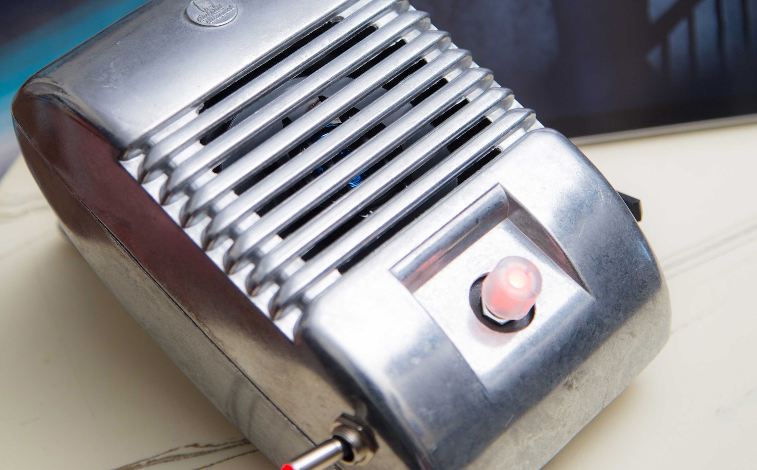
When I was a kid we went to the drive-in theater to see movies like The Legend of Boggy Creek and Evel Knievel. I loved those movies but I remember just as vividly those retro-cool metal speakers that entered into our car for these campy films. A few years ago I found one of these speakers at a flea market and it came home with me.

After it sat in my garage for years, I finally decided it needed to be what it was made to be: a speaker. But this time it gets some pretty nice power and technology, as a 20-watt amplified stereo speaker set with an RGB lighted dial that first dials in your volume by color and then, with a click, pulses to the beat of the music. It’s all done with 4 modern off-the-shelf circuit boards inside — but to keep the retro look, there’s an old-school toggle switch for power.

Another thing I really like about this project is that we take some off-the-shelf maker kit work and apply it to a gift from the past and make it new again.

YouTube player

Hardware

Arduino Pro Mini: As with most of my hardware projects, I start with a standard Arduino. Of course, the standard Arduino board isn’t going to fit into this case and designing a custom board is time-consuming and expensive. The solution for many projects is to use one of the small Arduino boards available. I used the Arduino Pro Mini and it was perfect for this project. It’s inexpensive, very small, and reliable.

Adafruit Stereo 20W Class D Audio Amplifier – MAX9744 board: One of the things I really needed for this project was the ability to control the volume digitally. After hunting for a while I settled on the Ada Fruit MAX9744 board. This beautiful little board gave me everything I needed in a small package and it sounds awesome.

Adafruit Electret Microphone Amplifier: This optional finishing touch provides modulation of the color of the LED to the beat of the music. This is accomplished by using this little mic board to listen to the music, then filtering the analog signal to detect the beat (thanks to some existing open source Arduino software). This mode is enabled and disabled by clicking the encoder.  If this mode is not wanted, simply omit it from the project and everything else will work just fine as-is.

Sparkfun RGB Encoder breakout board: This little board makes the addition of the RGB encoder easy for this project.

What will the next generation of Make: look like? We’re inviting you to shape the future by investing in Make:. By becoming an investor, you help decide what’s next. The future of Make: is in your hands. Learn More.

Project Steps

1. BUILD THE ADAFRUIT AMPLIFIER

Figure A. Step shots by Dan Rasmussen

Follow the manufacturer’s instructions for Digital Input, except don’t install all the header pins; install only those for SDA, SCL, Vi2c, SHDN, Mute, GND, and VDD (Figure A)

2. PREPARE THE ARDUINO PRO MINI

Figure B
Figure B

Solder the headers on (Figure B), then download the project code file DriveIn.ino, and upload it to the Arduino.

TIP: Find or draw a diagram of the pin markings on the Arduino, because they’re difficult to see after the headers are installed.

3. SOLDER RGB ENCODER TO BREAKOUT


Insert the encoder into the side of the board labeled RGB, then solder the headers on the opposite side, labeled RG (Figure C).

NOTE: It’s easy to mistakenly use the wrong side of the encoder breakout board. Be sure to assemble as shown.

4. SOLDER HEADERS TO MIC BOARD

Figure D
Figure D

Solder the 3 header pins on (Figure D).

5. WIRE THE POWER CONNECTIONS

Figure E
Figure E

Wire the toggle switch and barrel jack following Figure E. Note that the switch has been wired to illuminate only when power is switched on. It can also be wired to always illuminate (see Adafruit’s instructions).

Connect the loose power and ground wires to the amplifier board’s 12V + and – screw terminals. Later we’ll use the amp’s VDD output pin to power the Arduino.

6. MOUNT THE BOARDS FOR TESTING

Figure F

You can use the Scotch fasteners to attach your boards to a work area for wiring and testing. Apply a section of fastener to the underside of each board (Figure F), then apply another fastener to a test mounting board (some stiff cardboard is fine).

You’ll use the same fasteners to mount these inside the speaker housing.

7. PREPARE THE ENCODER WIRES

DSCF2688
Figure G

The RGB jumper wires each require an in-line resistor, 150-ohm ¼-watt. Assemble as shown in Figure G, then seal the joint with heat-shrink tubing. I like to add an extra piece of wire (disconnected) inside the heat-shrink to stiffen the joint.

Figure H
Figure H

Additionally, a pull-down resistor is required for the encoder’s integrated switch. This one is a 10K. Assemble as shown in Figure H, then seal the joint with heat-shrink tubing.

8. CONNECT THE ELECTRONICS

Figure I
Figure I
Figure J
Figure J

Follow the diagrams in Figures I and J to connect the amp, Arduino, encoder board, and RGB LED. Be as neat as possible; it will make final assembly much easier.
Connect your speakers to the amplifier’s Left and Right screw terminals. Connect your (optional) microphone board’s GND, 5V, and Out pins to the Arduino’s GND, 5V, and Analog pin 2, respectively.

After the wires are in place, use tape to manage the plug ends and the wires. It’s important to get the wires from the encoder board nice and flat, so they’re easy to reconnect. I used packing tape to group them into a little ribbon cable.

9. CHECK YOUR WORK

Figure K
Figure K

Verify all your connections, then plug the DC power supply into the barrel jack. The switch should light up when you turn it on. You should also see the LED encoder knob light up (Figure K) and cycle through red, green, and blue before settling on its default volume color level — a good indication that all is well.

Plug an audio input source into the amplifier board using one of the audio patch cords. Be sure your input source volume is turned up to a moderate/high volume. Now you should be able to control the speaker output volume by using the encoder dial.

Try turning the encoder’s shaft — you should see it change color. Click the encoder, and you should see the light modulate with the music (if you’re using the mic). Click again and it should to return to your solid volume color.

10. PREPARE THE SPEAKER HOUSINGS

If you’re using vintage housings, disassemble them and remove all components. You only need to retain the housing and screws.

Figure L
Figure L

If you’re using reproduction housings, you might want to tap the speaker mounting holes to accept machine screws (Figure L). (You can use the self-tapping screws that the housings came with but these may eventually strip out.) I got a cheap tap set from Harbor Freight and used the metric 8-32 tap and M8 screws. Go slow, and use a bit of tapping oil or WD40 for lubrication. Remove and clean the tap often as you go.

TIP: Some vintage speakers were assembled with security screws — these may have to be drilled out, or they may be big enough that you can cut a slot in the top for a screwdriver, using a Dremel and mini cut-off wheel.

11. DRILL THE LEFT HOUSING

DSCF2677
Figure M

The left speaker housing needs 3 holes drilled in the front half of the casting (Figure M), sized to fit your hardware and speaker wire: at bottom left for the on-off power switch, bottom right for the power jack, and top right for the wire to the second speaker. Placement doesn’t have to be perfect.

TIP: Because these aluminum castings can crack or shatter, don’t use a punch to mark the location of the holes. Instead, mark them with a Sharpie, carefully make a dimple using a very small drill bit, then finish each hole with the final bit. These castings drill easily using a nice sharp bit and moderate pressure.

Figure N
Figure N

If you’re going to paint your speakers, now is the time. Apply 2 thin coats of primer and then 2 or 3 thin coats of paint (Figure N).

Optionally, add a grommet to the speaker-wire hole and the original rear hole (for your audio input cord) for a more finished look.

12. MAKE THE MOUNTING PANELS

To fit the circuit boards neatly into the left housing, you’ll use mounting panels made from 1/8″ (0.125″ or 3mm) fiberboard. Download the template here to cut your own.

For the left speaker, tape or glue the small horizontal shelf to the large vertical panel, using the 2 corner braces. For the right speaker, you only need a vertical panel.

I recommend painting the front flat black to prevent it showing through the grill.

13. MOUNT THE ELECTRONICS

DSCF2632 2
Figure O

On the vertical panel, mount the encoder in the center hole at the bottom (Figure O) using its included nut. (It’s easiest to disconnect the encoder and mic boards before mounting.) This panel also serves as a spacer, since our speakers aren’t exactly the same size as the vintage ones.

Figure P
Figure P

On the horizontal shelf, use the Scotch fasteners to mount the Arduino and amplifier board on top (Figure P), and the mic board underneath. Place the amp board carefully to avoid interference with the top of the case.

Remove the 3 circuit boards temporarily and slide the mounting panels into the case. Then mount the speaker, DC power jack, and power toggle switch.

14. CONNECT THE RIGHT SPEAKER

Mount the right speaker in its housing, using a second vertical panel as a spacer.

Figure Q
Figure Q

In the left housing, attach your speaker wire to the Right output terminals of the amplifier board, and run it through a self-adhesive cable tie mount to provide strain relief (Figure Q). Then thread it out through its grommetted hole, and solder it to the 2 hookup wires provided with the speaker.

15. ADD THE AUDIO INPUT CORD

Cut one end off an audio patch cable and thread it through the original audio cord hole in the back half of the casting. Again, use a cable tie mount for strain relief. Then connect its 3 wires to the R/–/L audio input screw terminals on the amplifier board, using your voltmeter to determine which wire goes to the tip/ring/sleeve of the cable (test for near-zero resistance). Attach the tip to L, the ring (next section behind the tip) to R, and the sleeve to ground (–).

Figure R
Figure R

Press your circuit boards back into place (Figure R) and double-check connections. Close up the cases, push the clear knob onto the encoder shaft, and enjoy!

Passion Pit Playlist

DriveInEQMusic-1

Hang your drive-in speakers somewhere fun, then connect your audio source. This little 20W amp provides a lot of sound!

The encoder dial will change colors as you turn the volume up and down. Now click it to make the light pulse to the beat; the little microphone board listens to the music, then the Arduino filters the analog signal to detect the beat (thanks to some open source software) and modulate the light.

Going Further

I considered Bluetooth wireless audio input, but found that it was a relatively expensive and complex addition to the project. You could try plugging a car Bluetooth adapter (e.g. Amazon #B00LVFPXNC) into the amp board, but I suspect the metal housing might interfere. I’d love to see your solution!

Either way, these amped-up drive-in speakers are a super cool way to groove to some retro (or not so retro) tunes.