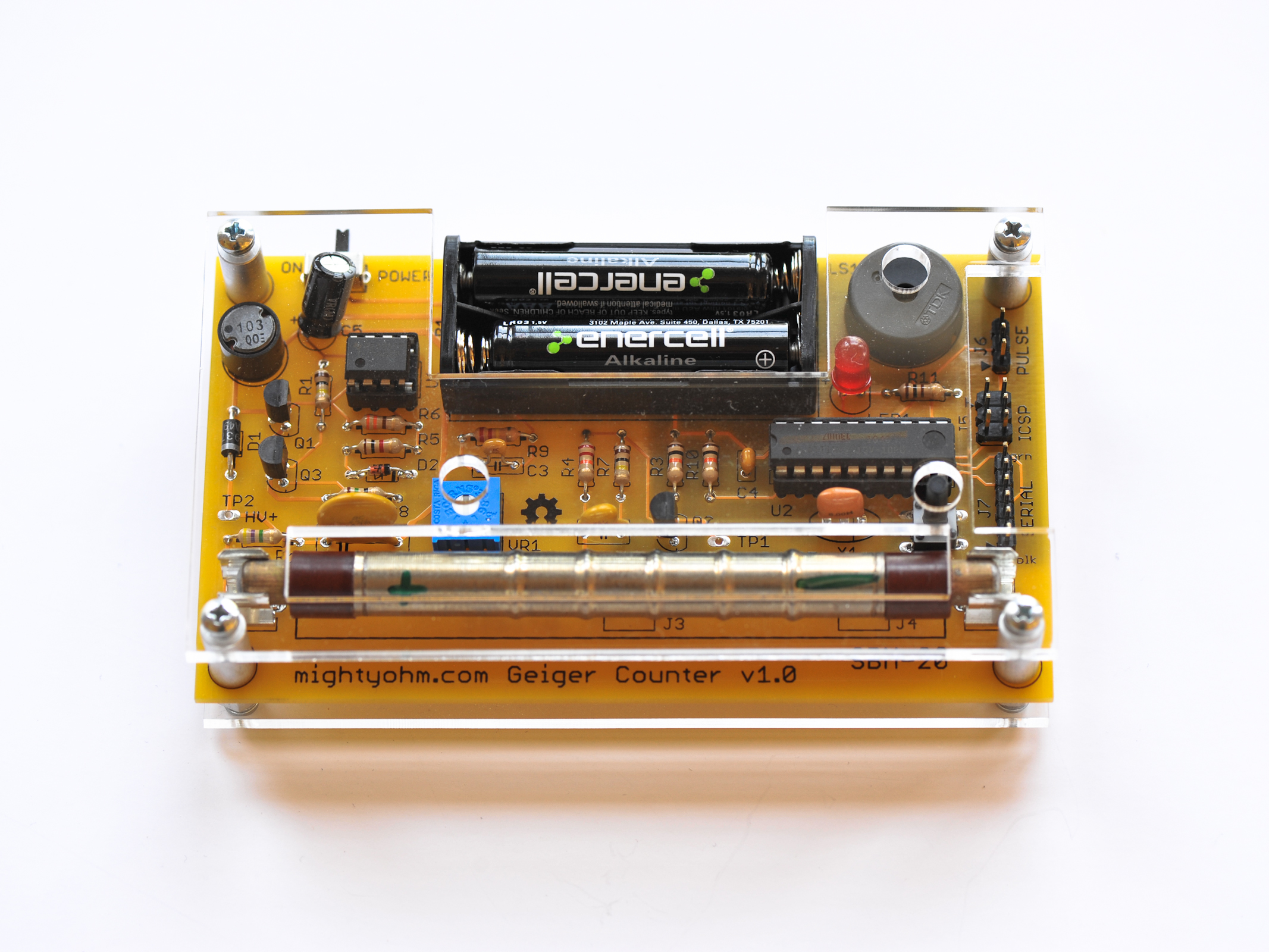
Commercial Geiger counters can cost hundreds of dollars. Build your own at a fraction of the price! This easy-to-solder kit can be built in an evening and it works just like you think it would; clicking and blinking in the presence of radiation. Just follow the instructions here to build it and use it.

Your MAKE Geiger Counter Kit features:

  • Detects beta and gamma rays
  • Serial logging output
  • Mute button
  • LED indicator
  • “Clicker” speaker
  • Pulse output
  • ATtiny2313 microcontroller
  • SBM-20 Geiger-Müller tube
  • Runs on two AAA alkaline batteries (not included)

Is grandma’s dish collection radioactive? Do bananas give off radiation? Are your granite countertops giving off gamma rays? Build your own Geiger counter and find out! The serial logging function lets you easily track exposure over time, and the mute button lets you silently detect radiation. A must for every mad scientist.

WARNING: This Geiger Counter kit is for EDUCATIONAL PURPOSES ONLY. Don’t even think about using it to monitor radiation in life-threatening situations, or in any environment where you may expose yourself to dangerous levels of radiation. Don’t rely on the collected data to be an accurate measure of radiation exposure. Be safe!

What will the next generation of Make: look like? We’re inviting you to shape the future by investing in Make:. By becoming an investor, you help decide what’s next. The future of Make: is in your hands. Learn More.

Project Steps

Solder the resistors.

To build this kit, you should know how to solder. And it’ll be much easier if you’ve made other kits before. But even if this is your first kit, don’t despair! Just take your time and you’ll be fine.

If you’ve never soldered before, Andie Nordgren, Mitch Altman, and Jeff Keyzer of MightyOhm made a fun comic book that will teach you how. You can find it online, translated into many languages, at mightyohm.com/soldercomic.

We recommend soldering one resistor at a time unless you know what you’re doing!

The resistors can go in either way — they’re not polarized. Bend the leads of each resistor straight down and push them through the holes in the board, then bend them out at a 45° angle to keep the resistor from falling out.

Turn the board over, and solder each lead. Then, cut off the excess leads with your wire cutters.

Solder the diodes.

Diodes are polarized, so they have to go in the right way. Make sure the stripe lines up with the black band shown on the board!

D1 is larger, and black with a white stripe.

D2 is smaller, and reddish-orange colored, with a black stripe.

Both are labeled with the part number, although it can be hard to read.

Solder the slide switch (S1).

Make sure it sits flat on the board with the plastic lever sticking off the edge. I like to solder one of the end tabs, then reflow the solder and push it flat with my finger (don’t leave the soldering iron on it too long, or you will say “ouch!”)

Be sure to solder both tabs on the ends as well as the 3 leads.

Solder capacitors C3, C4, and the variable resistor (VR1).

Both of these capacitors are very small. C4 goes next to U2 and is marked 104. It’s the very tiny capacitor with narrowly spaced leads (2.5mm).

C3 is marked 102 and has wider spaced leads (5mm).

The variable resistor is easy to find — it’s blue with 3 leads.

Solder the transistors.

First, solder Q1. It’s marked J3303. Make sure the flat spot of the transistor lines up with the markings on the PCB. You’ll need to bend the leads slightly to get them into the holes.

NOTE: Don’t push the transistors all the way down against the PCB — leave a few millimeters gap.

Solder Q2 and Q3, marked 3904. Make sure you put them in the right way, following the markings on the board!

Install the headers (optional).

If you want to log data or hack the kit, install the headers J5, J6, and J7.

J5 is the double-row header (2 rows × 3 pins).

J6 and J7 are single-row headers. Carefully break the supplied header strip into 1 strip of 3 and 1 strip of 6 pins, using pliers or wire cutters.

When soldering the headers, it’s a good idea to solder one pin first, then make sure the header is straight, and then solder the rest of the pins.

Solder capacitor C2 and the ceramic resonator X1.

C2 is marked 221K and sits up above the PCB a little bit.

X1 is marked 8.00M or 8.0MC and has 3 leads.

Both of these can be installed in either direction — they are nonpolarized.

Solder IC sockets U1 and U2 and pushbutton S2.

U1 and U2 pop into place and are easy to solder. Make sure the notch in the socket aligns with the notch in the silkscreened image on the PCB. You don’t need to clip the leads, they’re already very short.

Important: If you’ll mount your Geiger counter in the included acrylic case, use the pushbutton that comes with the case hardware (it has a long shaft) and solder it last, after all the other components!

The pushbutton can go in either way. No need to clip the leads on this either.

Solder the inductor (L1), the piezo (LS1), and the electrolytic capacitor (C5).

L1 is the black cylinder marked 103. It can go in either way.

LS1 is the large, short cylinder with a hole in the middle. It can go in either way.

C5 is the large black capacitor with a white stripe on one side — that side is negative and goes away from the + symbol. Make sure you install this one in the right direction, because it’s polarized. Push it all the way down against the PCB. You might have to wiggle the leads a little bit.

Solder the tube holder clips.

These are the small metal clips. Positions J1 and J2 are the furthest apart; use these for the SBM-20 Geiger tube included in the kit. To substitute shorter tubes, you can put the right-hand clip into different positions.

Solder one lead of the clip, make sure it’s straight, and then solder the other lead.

Solder the LED and ceramic disc cap (C1).

The LED is polarized, so be sure to put it in the right way. It will sit up a bit above the PCB.

The longer, positive lead goes into the hole marked +, and the flat spot on the side of the LED indicates the shorter, negative lead (just like the drawing on the PCB).

Solder one lead, check to make sure the LED is sitting straight, and then solder the other lead.

C1 can go in either way.

Solder the battery holder.

Make sure it’s straight, cut off the excess leads (watch your eyes!), and insert the small screw into the hole in the middle. Flip the board over and install the small nut. You’ll need a small screwdriver, but you can use your fingers to hold the nut.

Install the integrated circuits (U1 and U2).

You’ll need to bend the IC pins inward slightly to get them to fit into the sockets. Be careful! You don’t want to push too hard and wind up with a pin bent and sticking out of the socket — maybe into your finger!

Very important! Make sure the notch and/or small dot on each IC goes toward the notch in the socket (on the left, if you’re looking at the board with the text right-side-up). The ATtiny2313 has a large dot and a small dot on top — the small dot goes closest to the notch (pin 1).

The TLC555CP chip goes into the socket for U1.

The ATTINY2313V chip goes into the socket for U2.

Handle these parts carefully, as they’re static sensitive.

Install the Geiger-Müller tube.

Important! First, use a pair of needlenose pliers to bend the tube clips apart slightly, so they aren’t so tight on the tube. Then carefully insert the tube. It is polarized, so make sure the + mark or CBM20 label is on the left side of the board, closest to the tube clip marked +.

CAUTION: Don’t push too hard on the Geiger tube, or drop it – it is very fragile. If the clips are too tight, stop and bend them outward slightly, then try again. Don’t force the tube into the clips or you will crush it.

Test it!

WARNING: This kit is capable of generating high voltages (300V–600V). Don’t touch any part of the circuit (particularly the bottom of the PCB) while it is on! The current is low, so while the potential for injury is low, it may startle you and cause you to drop your kit (and break your Geiger tube!).

Make sure the switch is off (away from the ON position). Then insert two AAA batteries in the battery holder.

Use a small screwdriver to rotate the adjustment on VR1 all the way to the left (CCW) and turn on S1.

Listen for clicks and watch the LED. Slowly, rotate VR1 clockwise until you hear clicks. Once you start to hear clicks, rotate VR1 about 45° more and stop.

You’re done!

If you have a multimeter with a very high input impedance (1 gigohm), you can measure the voltage from ground to TP2 – it should be about 400V.

If you have an ordinary digital multimeter (DMM), you can get a 1 gigohm (1GΩ) resistor and put it in series with your DMM, then multiply the reading by the ratio [1,000 / (the internal resistance of your DMM in megohms)].

Assemble the case (optional).

Now’s the time to install the tall pushbutton switch that comes with the case (instead of the short one from Step 8). Solder it at S2.

Remove the paper backing from the acrylic top and bottom plates. Use your fingernail, not anything metallic or sharp, because the acrylic scratches fairly easily.

Install the standoffs on the 4 corners of the PCB. The longer, round standoffs go on top of the board, and the shorter hex standoffs screw into them through the bottom. Finger-tight is OK, just make them snug.

Secure the bottom plate to the hex standoffs with a screw and lock washer at each corner. Tighten the screws until snug, but don’t over-tighten — if you do, you’ll crack the acrylic.

Turn the kit over and install the top plate with the remaining screws and lock washers. Again, don’t overtighten the screws.

You’re done!

Cleaning the case: Use a soft cloth (microfiber is best). Gently wipe the case clean, being careful not to scratch it. If necessary, you can remove the cover plates and wash them in soap and warm water. Never use alcohol or ammonia-based cleaners (such as Windex) as they will damage the acrylic and may cause it to crack.

Pimp your Geiger: add a superbright LED (optional).

Want to give your Geiger Counter Kit a little more sparkle? Replace the ordinary indicator that comes with the kit with something special: a superbright LED! Follow the directions at MightyOhm.

Use the Geiger Bot app (optional).

Got an iPhone or other iOS device? Here’s how to use the Geiger Counter Kit with the Geiger Bot app on your iOS device. Nice!

Conclusion

How to Use It

Easy — turn on the switch and listen for clicks! And watch the LED: it will flash every time a beta particle or gamma ray hits the tube!

NOTE: The tube that comes with this kit is not sensitive to alpha particles. However, the kit is compatible with other tubes that do detect alpha.

Mute: If you get tired of hearing the clicks, you can push the button S2 to mute the sound.

Pulse connector: The pulse connector (J6) has the following pinout:

1. VCC (nominally 3V)

2. Pulse output — a short (100µs) active high pulse every time the Geiger tube fires

3. GND

For more information, design files, source code: mightyohm.com/geiger

Logging

To connect your computer to the serial port (J7), you'll need a USB-serial converter that operates at 3.3V TTL levels. The serial header is set up to work with the common FTDI-232R-3V3 serial cable.

Data is sent over the serial port at 9600 baud, 8N1. The data is reported in comma separated value (CSV) format:

CPS, #####, CPM, #####, uSv/hr, ###.##, SLOW|FAST|INST

There are three modes. Normally, the sample period is LONG_PERIOD (default 60 seconds). This is SLOW averaging mode. If the last 5 measured counts exceed a preset threshold, the sample period switches to SHORT_PERIOD seconds (default 5 seconds). This is FAST mode, and is more responsive but less accurate. Finally, if CPS > 255, we report CPS*60 and switch to INST mode, since we can't store data in the (8-bit) sample buffer.