Introduction

How would you or anyone you know like to generate their own electricity? How about generating enough electricity to accomplish a useful task like run a TV or a blender? Picture a party where people make their own frozen drinks. It is something most people never get a chance to try unless they happen to visit a science museum.

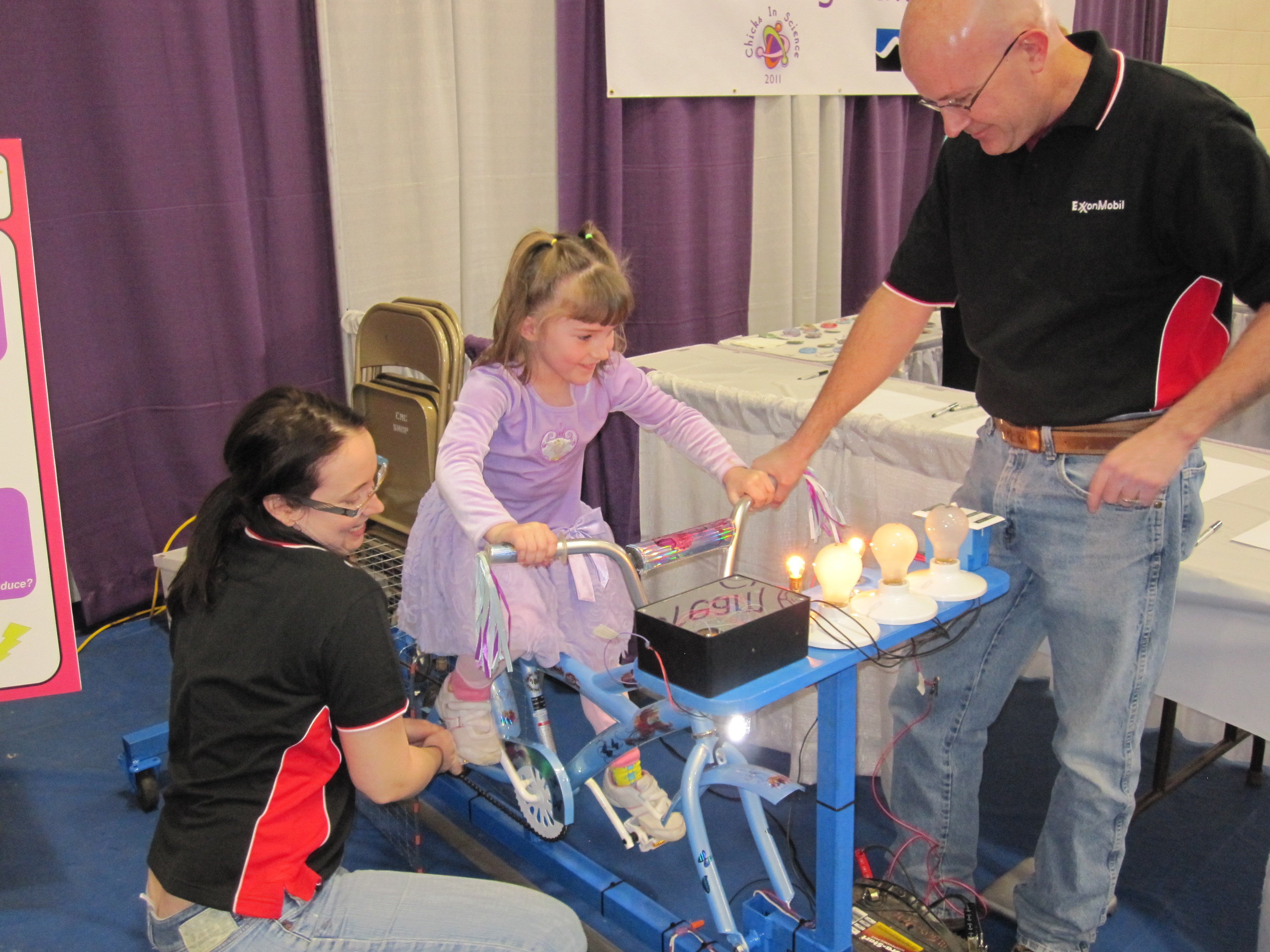
This article will walk you through building the generator bicycle shown in Figure 1. We have used the bicycle for two years as a hands on demonstration at the Chicks in Science Expo in Billings Montana, http://www.msubillings.edu/chicks/. It is a great way to introduce students to electricity, how it is generated, and how much work it takes to make a small amount of electricity.

Building a similar project might be of interest to a range of people. Educators will find it useful in providing context to lessons on electricity and the conversion of mechanical to electrical energy. Students will find it an interesting science fair or extra credit project that people are excited to try. Bicycle clubs or organizations sponsoring bicycle trail funding will find it a focal point of meetings and possibly use it to support fund raising activities. People interested in minimizing environmental impacts will be able to back out power from the grid and reduce CO2 emissions while powering a piece of equipment like a TV or computer while exercising. What a perfect way to earn some TV time by powering the equipment while you exercise.

Building the bicycle will utilize a number of skills including electronics, bicycle maintenance, either wood working or preferably welding, and maybe some metal working depending on the route you choose to progress. The project would be ideal for a general handyman or woman, or a small group who can bring various talents to the problem. Most experimenters will have access to much of the supplies needed to make a similar device, so you should be able to keep costs below $100 with a little ingenuity and a good spare parts bin.

What will the next generation of Make: look like? We’re inviting you to shape the future by investing in Make:. By becoming an investor, you help decide what’s next. The future of Make: is in your hands. Learn More.

Project Steps

I chose an automotive alternator for the generator for a few reasons. First they are inexpensive and readily available. I used a Delco 10SI that I had laying around the garage. You can find this type alternator on Ebay for as low as $30 including shipping.

You can also find low cost used or rebuilt alternators at wrecking yards, auto parts stores, or online. Amazon offers different style alternators for as low as $32 and offers free shipping.

The Delco 10SI is rated at 63 amps. At a nominal 12 volts, this is 756 watts or about 1 horsepower. A quick look at Granger.com for a comparable permanent magnet motor we could use as a generator yielded higher cost options.

Quarter horsepower and larger motors run in the several hundred dollar range. I would be concerned about burning up a generator smaller than a quarter horsepower, or about 186 watts, because people can generate more than this for a while.

A rugged design is another advantage of using an automotive alternative. Our service will provide no challenge to an alternator considering its normal operation of maybe 100,000 miles in all temperatures while being splashed with water and never being lubricated.

Another reason to use an alternator is the learning opportunity to tear into something so common in our industrialized lives. Although they are not overly complicated, there is some interesting electronics in the voltage control system housed inside the alternator.

I suspect most people don’t appreciate how an alternator controls voltage, but you will after experimenting with one or building a similar project.

Figure 2 is a photo of the alternator hooked up to a 12 volt RV light bulb and a drill press. An alternator is more complicated that you might expect when you first open it up. To make sense of things, I studied the internet then hooked jumpers from different points inside the alternator and reassembled it.

I could run the alternator at different RPMs on the drill press, and measure the jumpers with a voltmeter and oscilloscope. The effort is more than you need to do for this project, but it was interesting and informative.

Figure 3 shows the disassembled alternator. Electricity is generated as a magnetic field is rotated inside the stator coils. There are three stator coils, so the electricity generated is three phase alternating current. The three phase power is fed to the rectifier to generate direct current which is fed out of the alternator.

Voltage regulation in an alternator is achieved by controlling the strength of the rotating magnetic field. The raw three phase voltage is rectified in the diode trio and fed to the voltage regulator.

The voltage regulator is designed to maintain approximately 13.5 to 14.5 volts on the automotive electrical system for proper battery charging and system performance. Voltage is maintained by controlling current sent to the brushes and magnetic coils in the rotor.

Figure 4 shows the rotor. The slip rings slide against the brushes and create a circuit between the voltage regulator in the stator and the rotor coils. An interesting feature of the rotor is the single coil that creates an alternating magnetic field through the use of lobes on the rotor.

The alternating magnetic fields passing near the stator coils is what creates electricity.

The vision for the generator bicycle was to have a series of lights that would progressively turn on as the cyclist pedals harder. The alternator will generate more power and voltage as it is turned quicker.

What we need is a circuit that will monitor voltage on the main generator lead, and turn on more light bulbs as the voltage increases. There are a number of ways you could accomplish this including using a microcontroller. The easiest way I could come up with was to use an Op Amp as a comparator.

Figure 5 shows a schematic of the circuit. I use two 6 volt lantern batteries or an old car battery to provide a 12 volt reference. Resistors R1 through R5 form a voltage divider to provide reference voltages of approximately 4, 6, 8, and 10 volts.

These voltages are supplied to the low voltage side of four op amps in an LM324 quad op amp. The high voltage side of each op amp is connected to the main line from the alternator.

Output from each op amp will go high when the voltage from the generator exceeds the reference from the voltage divider. The high output from the op amp is fed to an indicating LED and to an NPN transistor. The indicating LED is optional, and was used for initial circuit testing.

The NPN transistor drives a 12 volt relay which feeds alternator power to a 12 volt 50 watt RV light bulb. There are 4 relay controlled light bulbs on the bicycle. There is a fifth bulb that is hooked directly to alternator power and is always “on.”

Resistor R7 limits current to the indicating LED. Resistor R6 limits current to the NPN transistor base. A diode is placed across the relay coil to prevent induction induced voltage spikes from damaging the NPN transistor. The circuit was built on a breadboard and is shown in Figure 6.

The circuit serves as a voltage regulator that controls voltage by adding or removing load to the system. Having all the lights hooked up all the time wouldn’t work well because the alternator would be under full load and starting to pedal could be overly difficult.

I had a tight timeline to make the bicycle in time for the science fair, so I chose to purchase the least expensive bicycle from Walmart for the project.

Walmart sells brand new 20″ bicycles for as low as $49 dollars which are nice because they are clean and easy to work on. Used bicycles are available for around $30 from places like Craigslist and pawn shops. There is a good chance you could get one for free that a friend’s child has outgrown.

Connecting the alternator to the bicycle is where your craftsmanship will come in. The easiest way is probably to have the back tire rub on a hub connected to the alternator. We opted for a chain drive with the bicycle mounted on a frame. Removing the front wheel and the kickstand provided two mounting points that support the bicycle.

A wood frame would be fine, but I prefer working with metal. If you are interesting in metal work, consider adding welding to your bag of tricks. There are plenty of books to teach yourself as I did, and it is a rewarding skill.

Harbor Freight sells entry level stick welders for $70 and MIG welders for $110. They run from a normal wall outlet. A welder is like a drill press. Once you have one, you will wonder how you ever got along without it.

Figure 7 is a photo of the generator bicycle layout on the frame. A chain transmission was use to gear up rotation speed. 70 RPM is a reasonable cadence for a bicycle rider. Figure 7 shows the teeth each sprocket has. Using ratios, we can estimate the alternator RPM as follows.

(70 rpm)x(40/18 teeth)x(48/14 teeth)x(43/16 teeth) = 1,433 RPM.

The gears were free from a local bicycle shop who provided a handful from a box of extra spare parts. Making the middle sprocket assembly took a little time, but might not be necessary.

My feeling is that the gear ratio is too high, and a lower ratio might be better. It might be a little easier for smaller kids. Children less than 7 or 8 years old have to work pretty hard to keep the bicycle going.

The frame is 2×2 inch box with 1/16 inch walls. The alternator pivots on the bottom bolt. A spring at the top holds chain tension. The center chain gave me fits jumping the sprocket, so I had to add a tensioner. I am not sure why some chains stay put, like the first one on the pedal, but the middle one didn’t.

A final touch was a poultry wire guard around the gears as a precaution to keep fingers away from the sprockets.

The chain drive was more complicated to construct than I might have liked. If I did it over, I would try having the back tire rub and turn the alternator shaft or remove the tire and use the wheel as a pulley. A quick check of alternator pulley showed it was approximately 2.5 – 3.5 inches.

Depending on the pulley design, it might service as a hub the tire pushes against to turn the alternator shaft directly. The bike wheel could also act as a pulley. Tractor Supply sells every size belt you can imagine and keeps a large stock.

Another option is building a hand cranked version. This could be mounted on a piece of plywood and clamped to a table with C-clamps. A hand crank could be built from a piece of 2×4 with a bolt for a handle. Consider using an inexpensive cordless drill for a gearbox.

Harbor Freight sells cordless drills for as low as $25. Another bolt on the 2×4 could be mounted in the drill chuck. The drill mounted on the plywood would provide a base to crank from and would contain the gearbox and permanent magnet motor which would serve as a generator.

All that would need to be done is interface the power from the drill to the lights and electronics of your choosing. The drill option might be small for a bicycle because the 1/4 horse power produced may be too much for the smaller drill motor.

The rotor coil is normally energized from the car battery until the alternator is up to speed and making power. The rotor takes about 4 amps, and represents 48 watts of current draw. We need a way to energize the rotor until the bike is up to speed.

What I chose to do was to use a 2 way switch that would supply the rotor from a battery at startup, then from the generator.

This worked good because young kids could get the bicycle up to speed with no power to the rotor and no load on the pedals. Once up to speed, I would flip the switch to battery to start power generation. Usually, the bike is started on battery then switched to alternator only mode.

The same battery supplies the 12 volt reference to the light control circuit. Figure 8 contains a schematic diagram of the rotor control switch. A 16 gauge wire is connected to the inboard brush.

The outboard brush is normally grounded. The wire is routed outside the alternator through a ventilation hole. The wire is hooked to a two pole switch such that it can be energized either with a 12 volt battery or from the main power lead from the alternator.

The last step to complete the alternator modification is to defeat the alternator’s internal voltage regulator. There is no need for it now, and it could complicate operations. I defeated the component by digging into the insulating pitch and snipping wires as shown in Figure 9. Reassemble the alternator, and you are ready to go.

This concludes the construction of the project. Figure 10 contains a parts list. Total cost is $185, but the figure assumes no attempts at saving, re-use, or salvage are made. The $67 price for the alternator is for a re-manufactured item similar to what you might buy at an auto parts store.

A salvage yard will charge $50, and $30 is a good target from Ebay or Craigslist. Perhaps you could get a damaged one for $10 from an auto parts store that was turned in as a core for rebuild. There is a good chance that the damage is in the electronics that you don’t need.

It is also likely that you should be able to get a bicycle cheaper than $50 for a new Walmart bike. A wrecked or very old bike should be available for closer to $10, and an outgrown child’s bike might be available free. The other larger cost is steel.

Steel prices have increased considerably over the last 10 years, but you won’t need much. If you know a backyard builder, a piece of scrap will do the trick.

Figuring out how to re-use and keep cost down can be part of the fun of doing a project. In my case I had the alternator and scrap steel. I purchased a bike as time was tight, but I should have shopped around. Most of the electronics I had in parts bins. I had to purchase the op amp, light fixtures, relays, and bulbs for a total cash outlay of $80.

I probably could have saved $30 on the bicycle and made it a $50 project. If your company sponsors a booth at the local science fair, they may be interested in reimbursing the expense.

The kids have had a ton of fun on the generator bike for two years running, and I am sure you would have a similar experience. That kind of hands on science is hard to beat, and the bicycle seems to be one of the more popular exhibits.

Most of the kids can light several of the bulbs, and even the first graders can light one or two. As the kids get older they can light all 5 bulbs and produce about 250 watts.

I haven’t seen anyone including adults that can produce that for very long though. I wonder what the efficiency of the machine is? If you produce 250 watts, how many watts are you actually supplying to the pedals?

Some photos and video of the event are included in the link in the introduction, and include shots of the generator bicycle. Additional photos are available at flickr.com by searching for “chicks in science.”

Feel free to drop the author an email at andrew.dennis.sullivan@gmail.com if you are considering a similar project and would like more background on our experiences.

What’s Next?

I started taking apart the alternator in support of a wind turbine project. My vision is to sculpt 3 blades and use a turbine to keep a set of batteries charged for a remote farm. We use batteries there now for electric fence and limited lighting.

More power would allow keeping animals year around because it would allow keeping water thawed. Out here in the high plains of Montana, there is plenty of wind. Running utility power is very costly.

Control of a wind turbine is more complicated. Voltage must be regulated to protect and charge the battery. The rotor current must be turned off in low wind or it will drain the batteries quickly. In low to moderate wind, rotor current will have to be limited to prevent putting too much load on the rotor and preventing it from spinning.

In high wind, rotation has to be limited to prevent catastrophic damage to the turbine. Sounds like a job for a microcontroller integrated with some solid hardware.