Clock radios are everyday hated devices that designers seem to ignore, judging by how little their features and user interfaces have changed. This project adds a new capability, letting would-be sleepyheads enjoy a human-machine interaction of a different sort. Don’t worry, we’re not going to connect your clock to an MP3 player and play mellow New Age sounds. We’re going to shoot the alarm off. With a gun. Wake-up time is now payback time.

We’ll base the project around a digital clock radio and a light gun for gaming; huge selections of both of these are available inexpensively second-hand, with many beautiful and well designed examples. To enable our FPSI (First Person Shooter Interface), we’ll outfit the gun with five tilt sensors, arranged at different angles on a small circuit board. A cable tethers the gun to the clock and carries your tilt and trigger signals to the clock’s time and alarm control button contacts.

Project Steps

Implementing gun control.

Our control circuit uses tilt switches to detect the gun’s position.

Tilt switches contain a metal ball or a conductive liquid (such as mercury) that rolls inside a small capsule. When the switch’s contacts point downward, the conductor bridges the contacts, closing the switch. Turn the switch upside down, and the conductor falls away from the contacts, opening the connection.

The tilt switches are arranged in a plane perpendicular to the gun’s barrel, to detect the approximate rotation of the handle when the gun is aimed forward (its “roll” in aeronautical terms). The gun doesn’t need to point at the clock to work (but it’s more satisfying that way).

The tilt circuit is wired into the clock radio to spoof three buttons: Alarm, Hour, and Minute. (We ignore the Snooze button.) Tilting the gun at different angles lines up connections through the tilt switches that bridge different buttons’ contacts. Pulling the trigger closes a shared ground connection, completing the connection as if you pressed the button (or button combination).

CAUTION: Do not work on the alarm clock while it is plugged in, or you risk serious and possibly fatal electric shock.

Open the clock radio.

Unplug the clock radio.

Disassemble the case. Carefully unscrew the four screws concealed by wells on the back, and separate the electronics from the plastic parts. To avoid damaging the plastic, choose a screwdriver that fits well, press down firmly, and turn slowly.

Marvel at the design details and quality! The shell is extremely well-crafted, with neat cavities for the screws and an elegant, raised icon for the power cord. The controls even resemble a face. This clock is full of design generosity, which is quite rare nowadays.

Untie the electric cable, and separate the electronic parts from the plastic shell.

Remember exactly how you took apart the electronics block and untied the electric cable, so you can put it all back together later.

Clean and shine it.

Use the paintbrush to clean the dust accumulated on the electronics.

Clean the plastic case with the toothbrush and kitchen soap. The bristles won’t damage or scratch the surface. Take your time to enjoy cleaning every corner! Let all pieces dry thoroughly.

NOTE: After the pieces dry, spray them with plastic polish, following the instructions on the can.

Wait a few minutes after spraying, then polish the surfaces with a clean cotton cloth. You’ll be amazed how new they’ll look! Now your alarm clock is ready for more serious work.

Drill the holes.

On the front half of the plastic shell, measure and mark a point to drill near the base and centered below the display. Protect the surface around the hole area with electrical tape, in case your drill skips away from its proper destination.

Find a drill bit that’s a bit thinner than your multi-conductor cable and drill the hole.

NOTE: This is the riskiest part of the work: drilling holes for the cable through the clock’s case. (I see some vintage collectors out there raising their hands in objection.)

Widen the hole with the round file. Keep widening slowly until the cable can just go through the hole with a bit of pressure. We don’t want a hole bigger than the cable.

Drill and widen a second hole in the plastic shell about 1″ to the left and slightly back from the first hole, in the interior wall that holds the battery case (see picture below right). The cable will enter the first hole and make a sharp left turn into this hidden hole as it routes its wires around to the back of the clock.

Attach the cable.

Strip about 16″ of sheathing off of each end of the cable, to reveal the color-coded wires inside. Pass one end of the cable through the holes you just drilled.

Use hot glue or another strong adhesive to fix the cable firmly in place, keeping the individual wires free inside the main compartment. Leave it neat and strong since this cable is going to be used.

Put the electronics block back into the front half of the case. Now we are ready to hard-wire the color cables to the clock switches.

Hard-wire the clock.

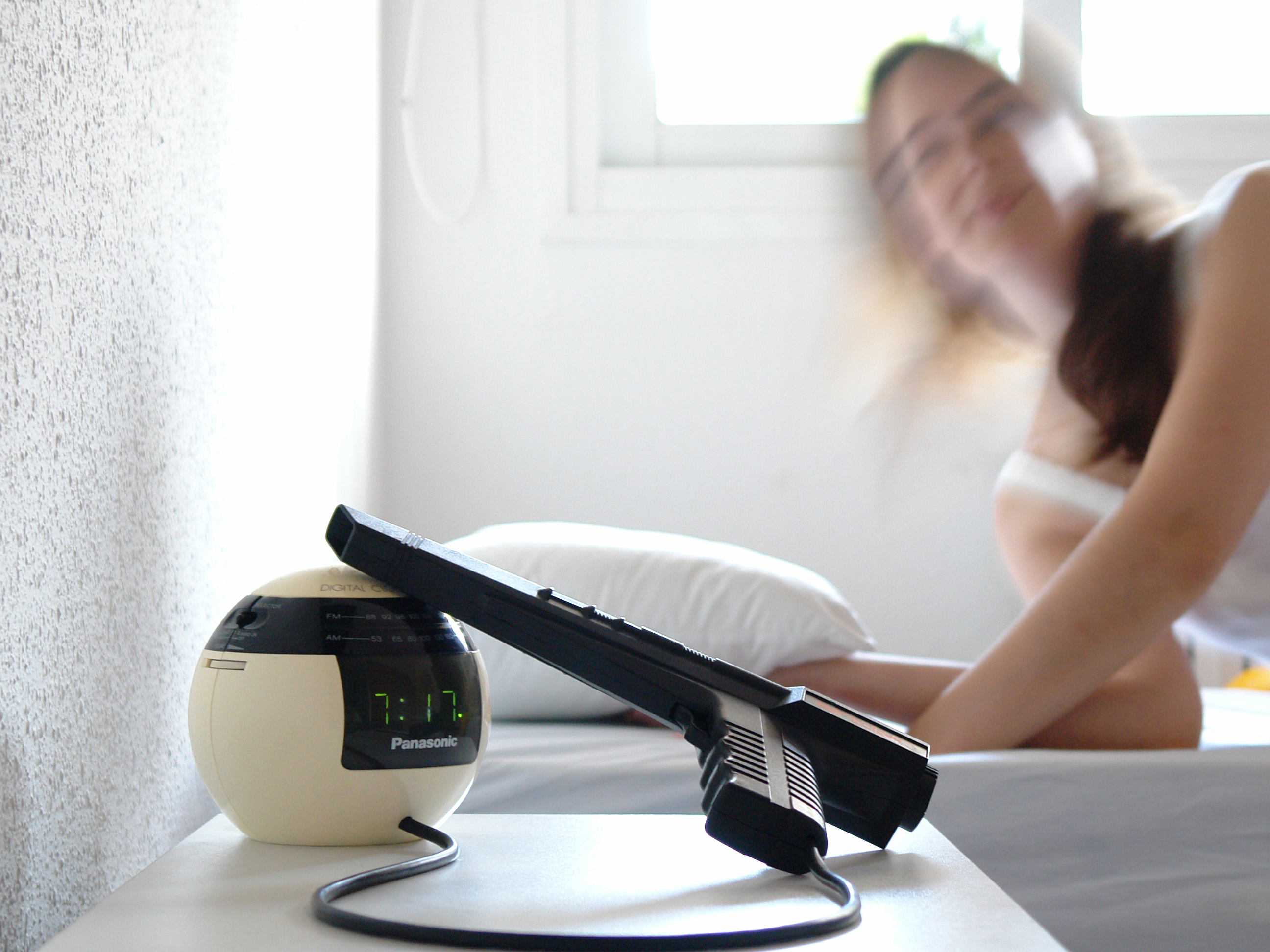
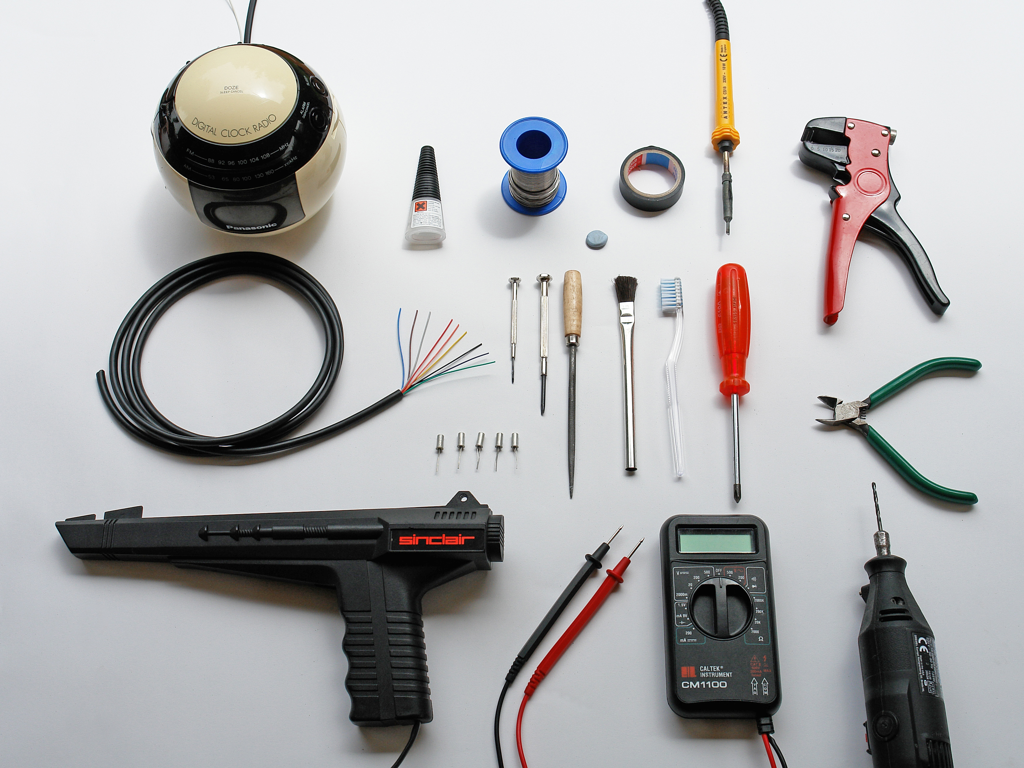
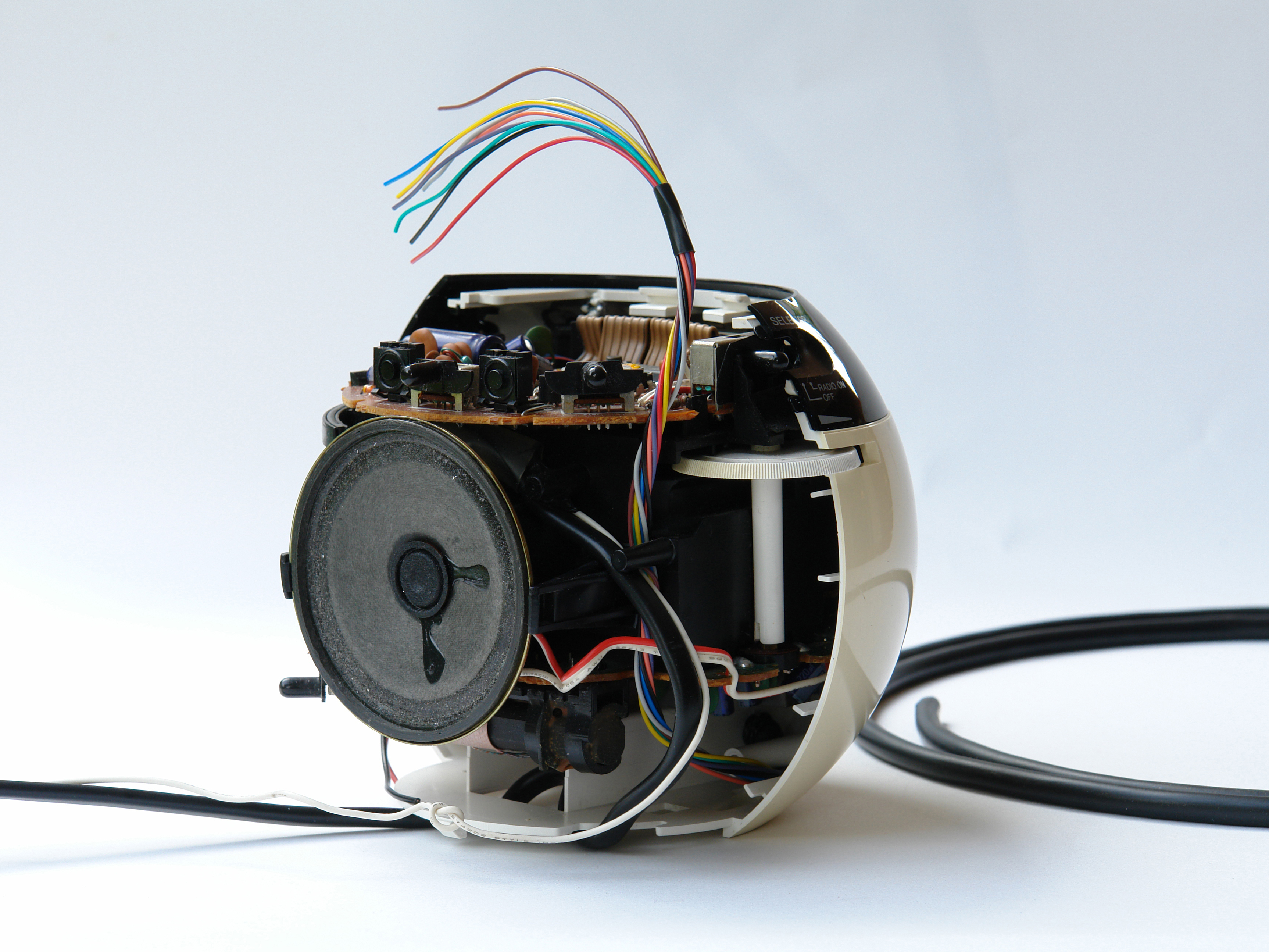
If you aren’t modding a Panasonic RC-70, don’t worry, because almost 99% of digital clocks work the same way. Just remember that each button has 2 connections, which come into contact with each other when you press the button. You want to extend these connections so that, instead of closing the circuit with the button, you’ll be using the light gun.

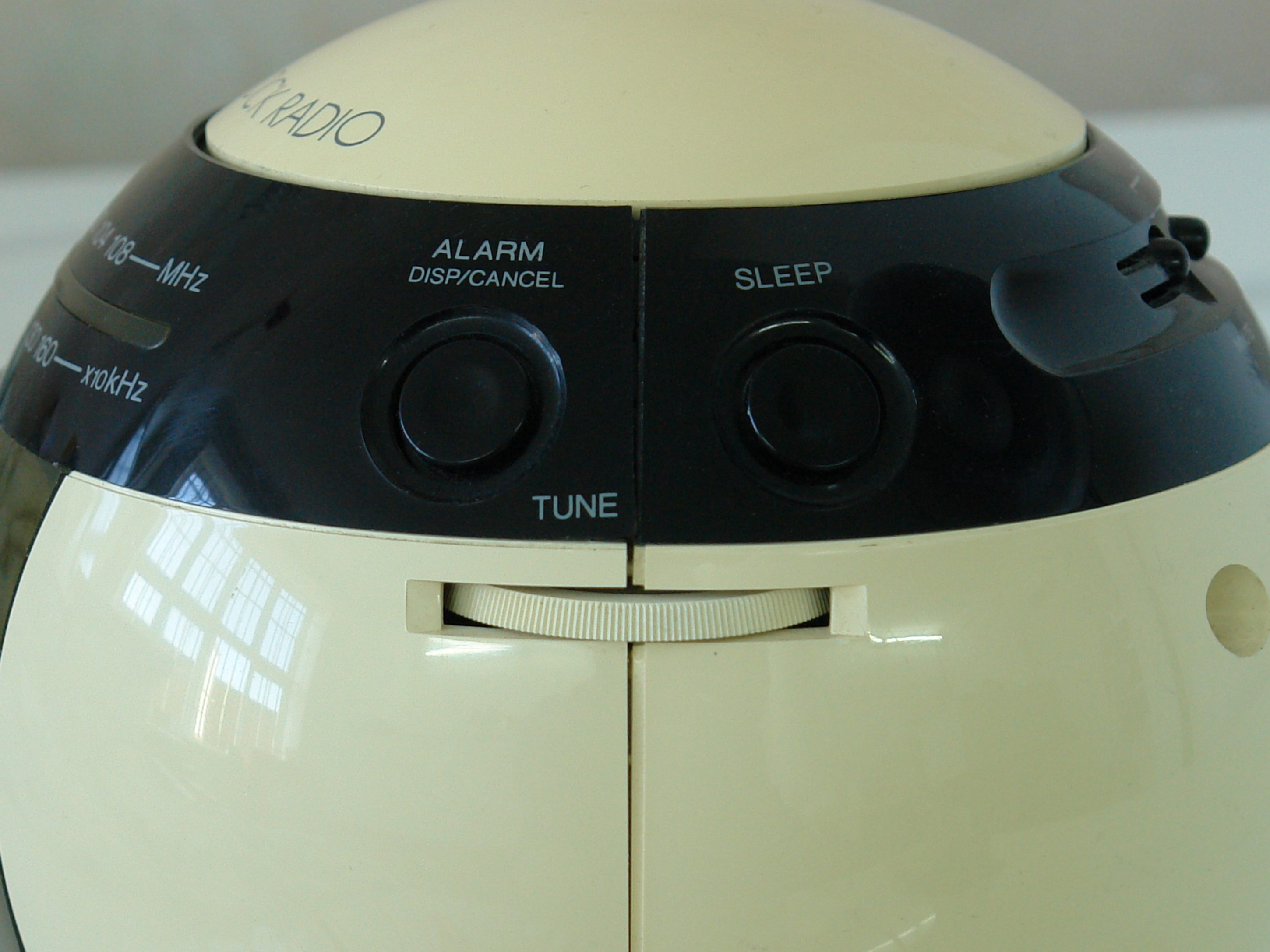
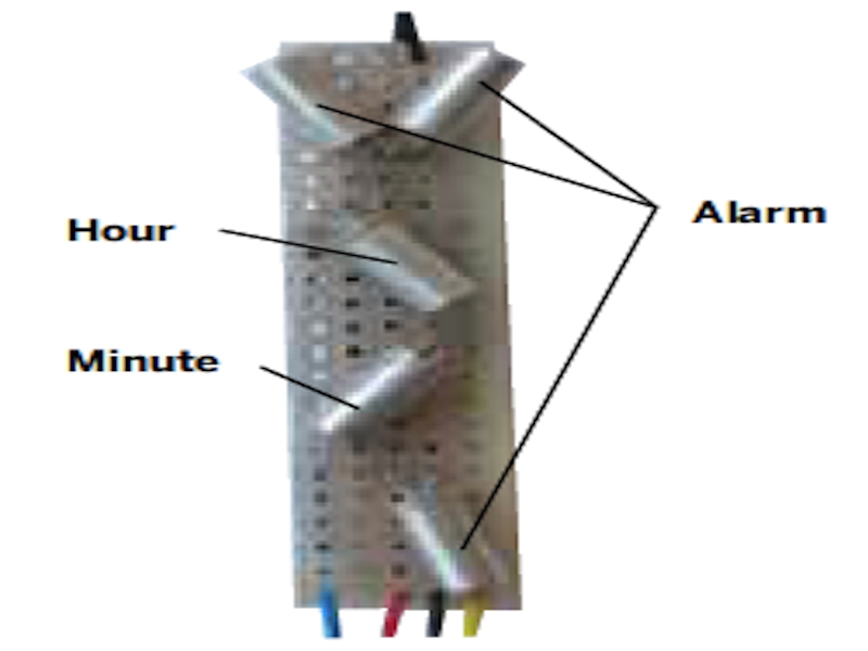
Find the buttons that control the essential functions: set time and alarm (hours and minutes), and alarm off. The RC-70 uses just 3 buttons for these: Alarm, Hour, and Minute. The Alarm button does double duty, shutting off the alarm and switching the Hour and Minute buttons from “time-set mode” (the default) to “alarm-set.” Some clock radios use a switch instead of a button to change between time-set and alarm-set modes.

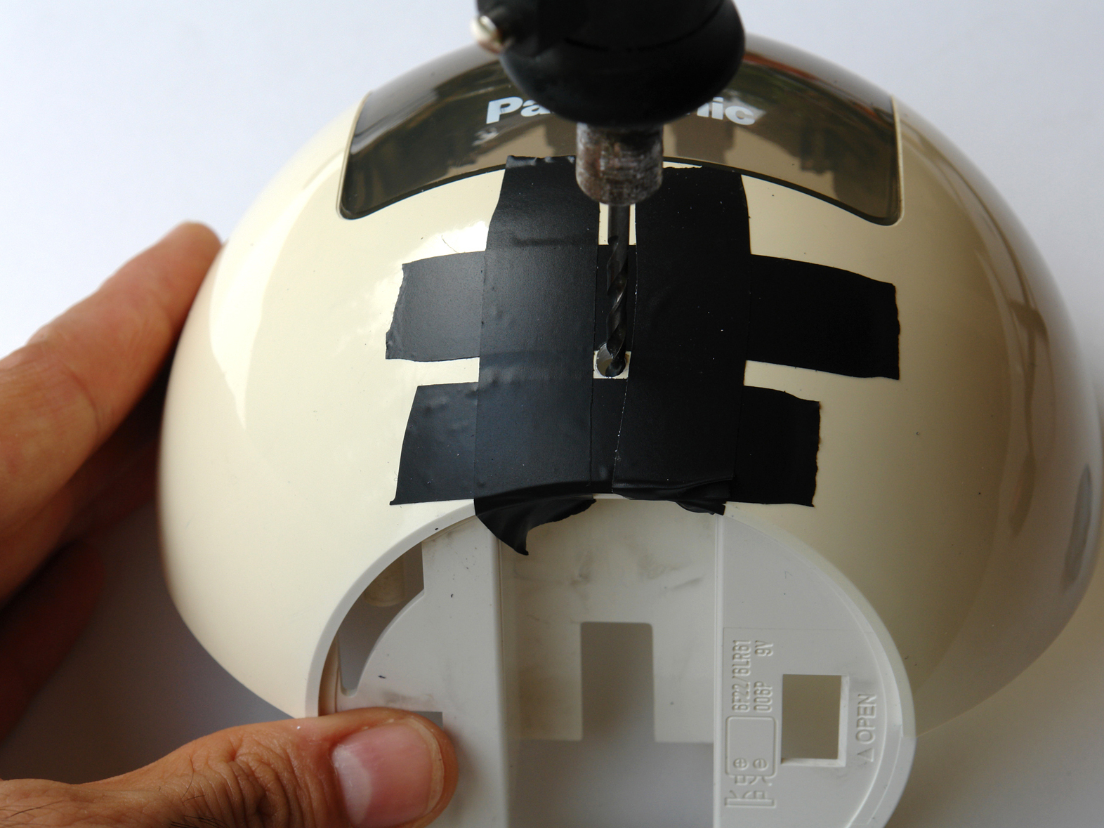
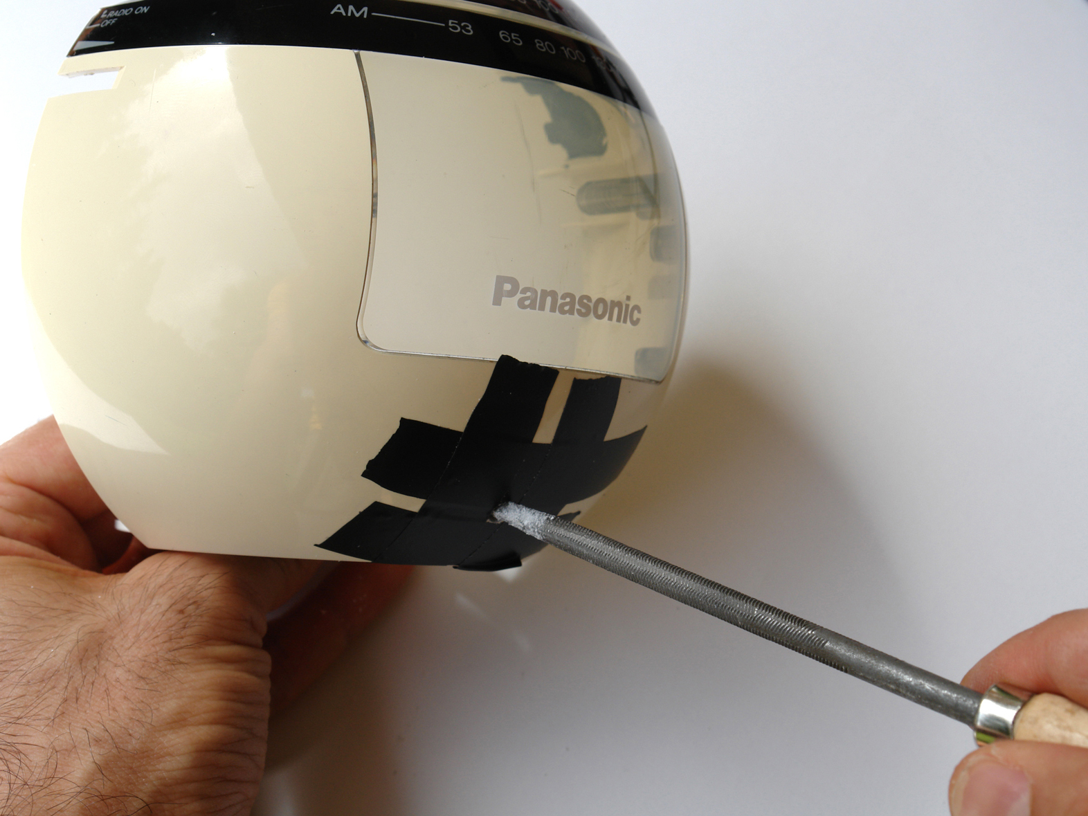
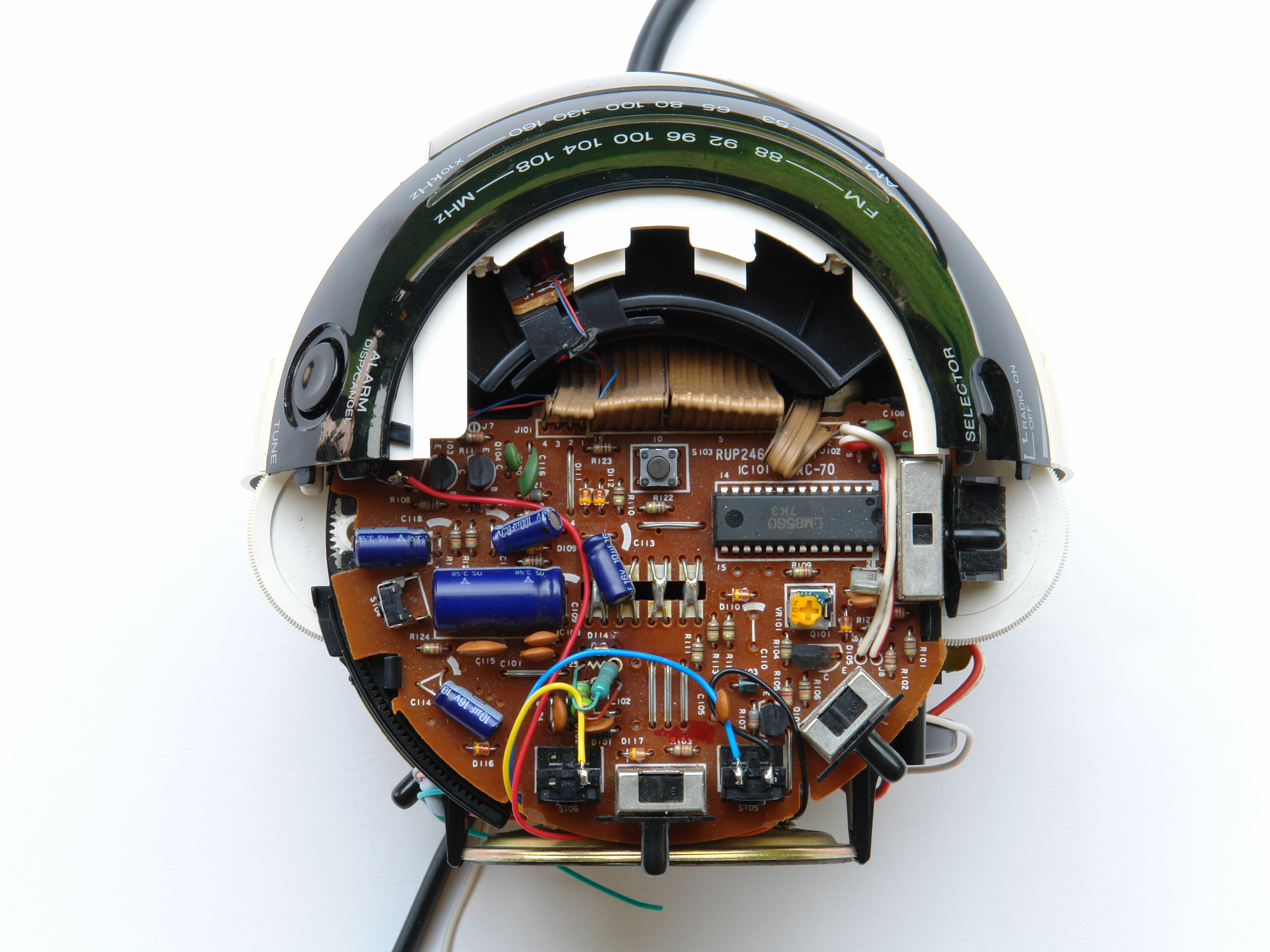
Locate the essential buttons’ contacts, 2 per button, and use a multimeter to follow each of them out to a solderable connection point. With the RC-70, all 3 buttons shared a common ground, so I needed to find a total of 4 connection points.

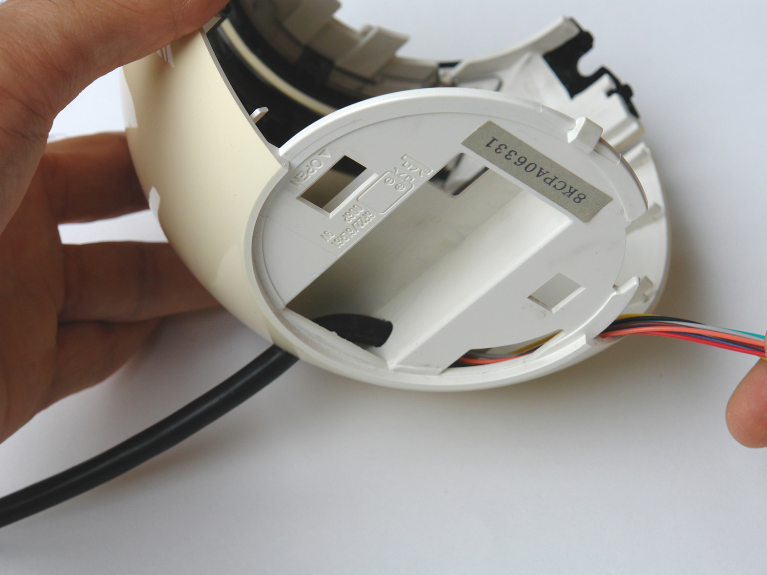
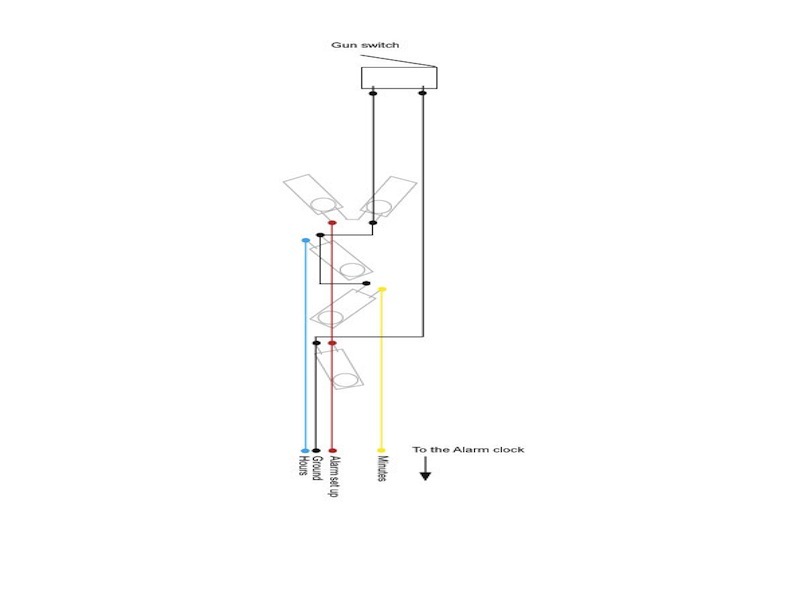
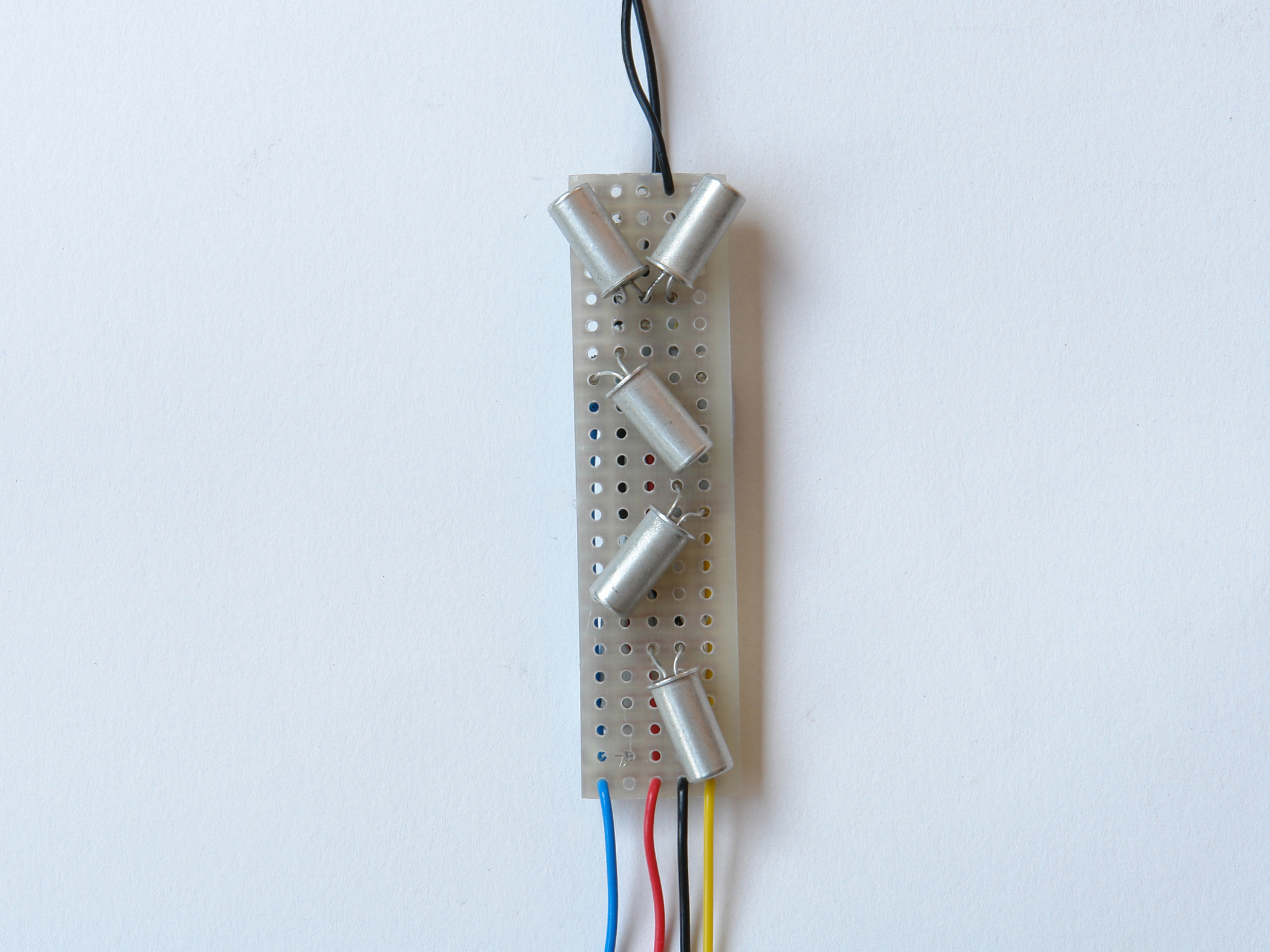
Solder wires from your cable to the contact points, using the color coding to track what goes where. Following convention, I connected the cable’s black wire to the shared ground, and designated colors for the 3 button-specific connections.

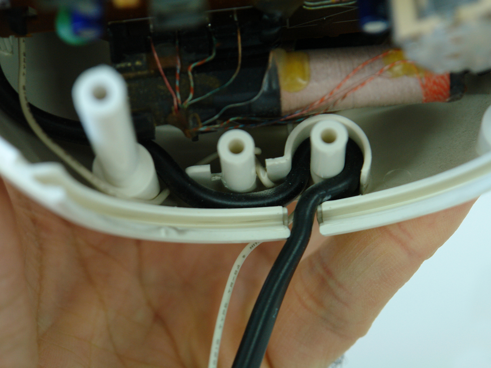
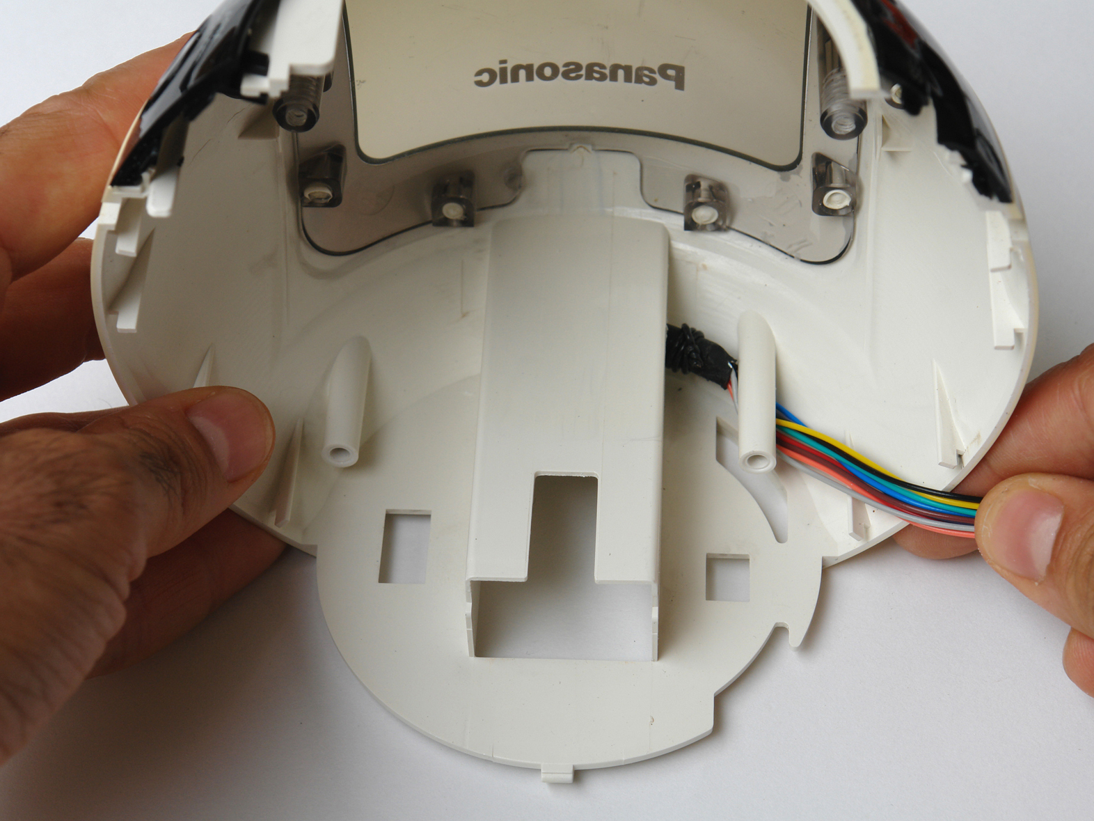
Organize and fix all the color cables between the free spaces of the clock. Trim extraneous cables to get them out of the way. Avoid placing cables near parts that get warm, such as the power converter.

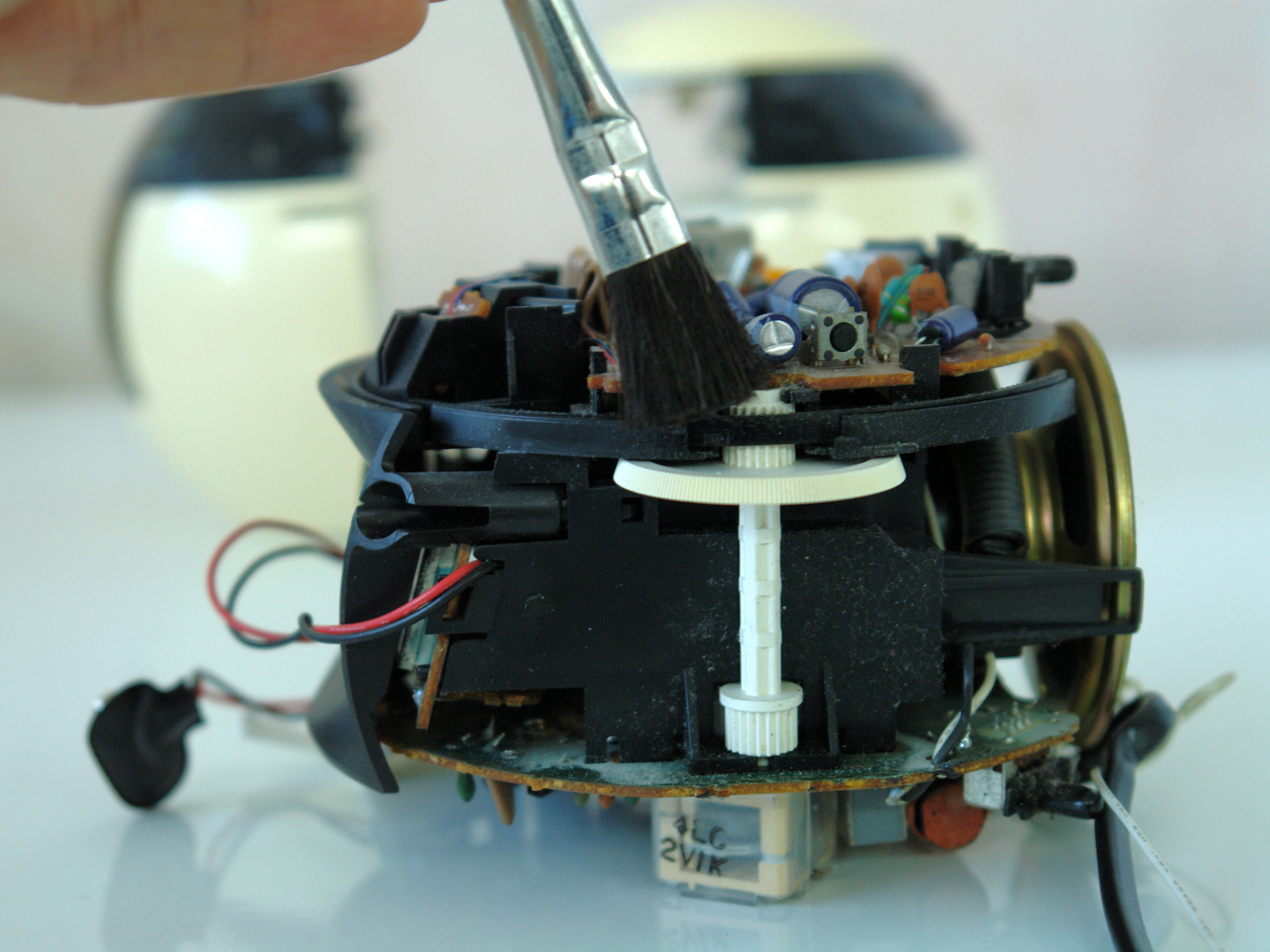
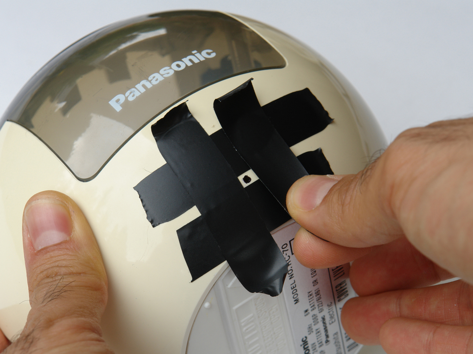
Reassemble the clock and screw it back together.

Test the clock by plugging it in and touching together the other ends of the cable wires you just soldered. Confirm that bridging the wires mimics the functions of the buttons you connected them to. If you didn’t make any big mistakes, everything should work! Don’t worry about touching the wires with your fingers, because the current going through them is very low. Once it’s working, unplug it again.

Hard-wire the light gun.

Take the light gun apart, and clean and shine it up the way you did with the clock radio.

Cut a rectangle of perfboard that’s big enough to carry the 5 tilt switches flat, but narrow enough to fit facing backward inside the handle. For my Sinclair Magnum, my board was about ⅝”×2⅜”.

If your clock radio is an RC-70 or work-alike, arrange the tilt switches on the perfboard as shown. Leave some extra room around each switch to let you bend and fine-tune their positions later.

Following the wiring diagram solder the tilt switches into place and connect them to the cable wires. Don’t worry about which sides you connect; the switches are functionally symmetrical.

Connect the ground to each sensor section and route it through the trigger switch contacts in the gun. To make my circuit more readable, I routed all wiring from the cable and trigger through the front of the board, at the edges. I also split 1 ground coming from the trigger and connected it in 2 places.

Re-assemble the gun.

Use poster putty to hold the tilt circuit in position inside the gun-half with the trigger. Plug in the clock radio, and test the interface by tilting and firing. Experiment with different firing angles, and bend the tilt switches around to refine their operation.

When the tilt switches work together properly, glue them in place, and then glue the circuit board into the gun handle. Re-assemble the gun.

Set the time, set the alarm to +1 minute, wait a minute, and FIRE!

Conclusion

This project first appeared in MAKE Volume 08, page 100.