

Switching plug-in appliances from your computer or microcontroller isn’t difficult in theory, but doing it without turning your home into a potential deathtrap can be tricky. The safer way is to rely on remote control rather than wiring directly.
Switching plug-in appliances from your computer or microcontroller isn’t difficult in theory, but doing it without turning your home into a potential deathtrap can be tricky. The safer way is to rely on remote control rather than wiring directly.

Here’s how I reverse-engineered and modified an inexpensive R/C power outlet switching system so that it can control a practically unlimited number of AC-powered devices wirelessly from a computer. This flexible setup lets me switch appliances on and off via the internet and run programs that switch them automatically at certain times of the day.
I had the idea for this project after buying a set of remote controlled power outlets from my local electronics store. Quite a few of these systems are available; they use radio frequencies, so you don’t need line-of-sight like you would with IR remote systems, and some are even housed in waterproof casings for installing outside. They all work on the same principle: you plug an appliance through the R/C outlet unit into a regular power outlet, and then the remote lets you switch power to the appliance on and off.
The set I bought has 3 outlet units and a remote control with On/Off buttons for each outlet, plus a master button pair that switches all outlets at once. You assign the buttons to the remote by pressing a Learn button on the outlet and then pressing the On button on the remote that you want to associate with it. If you wish, you can train multiple outlets to respond to the same button pair.
I was impressed by this system and was keen to expand it to control more than just 3 appliances. The instructions didn’t mention whether multiple sets would work without interference, but I noticed that if you left the remote’s battery disconnected for a while, you had to retrain all the outlet units.
The only explanation I could think of for this was that the remote generates a new unique identifier when it powers up, which the outlet units store during the learning process. If so, this was a good sign, as it suggested that you could co-locate 2 or more sets (and other similar devices), provided that their remotes used different identifiers.


So far so good, except that you’d still need a separate remote for every 3 units, which would get out of hand if you wanted to control a lot of devices. To find better alternatives, I opened up the remote control unit. The main circuit board housed button pads, an Elan EM78P153SNJ microcontroller (MCU), a 5V regulator, and an LED; underneath it sat another board with the radio transmitter circuit and antenna.
There was enough room inside the remote to hold a small microcontroller board. A microcontroller wired to the button contacts could then simulate button presses on the remote, and you could plug its USB interface into a computer to pass switching control over to the computer.
Also, the main board had unused pads for an extra pair of buttons, so it looked like you could easily wire the remote to control 4 devices instead of 3. By wiring into the remote like this, you don’t need to modify the power outlet units at all; they remain safely intact with all their approvals (FCC, CE, UL, etc.).
But 4 devices per remote still isn’t much, so I decided instead to try and intercept the data signals being sent from the remote’s microcontroller to the radio transmitter circuit on the board underneath. If I could decode these signals, then I could also generate my own signals and control lots more devices, if the protocol allowed it.


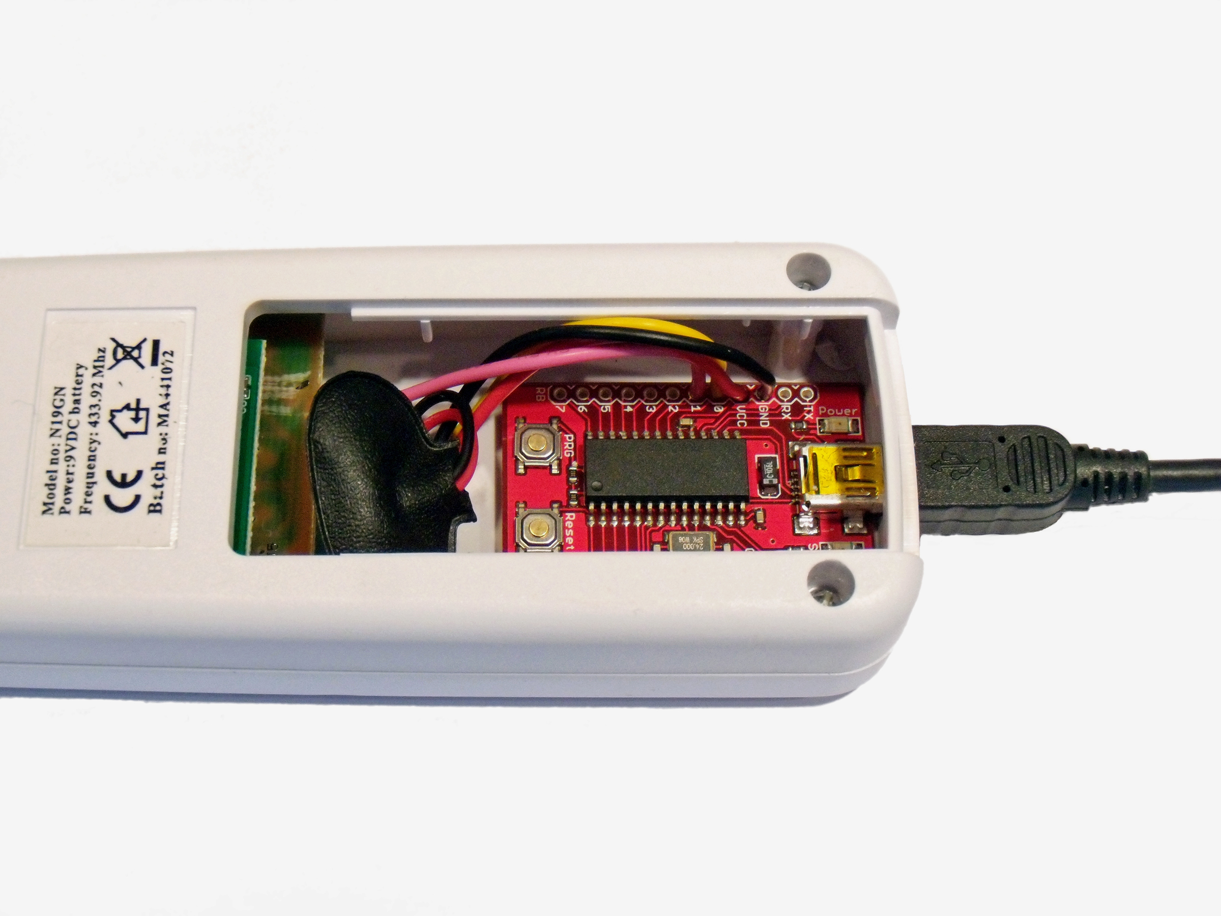
To decode and hopefully generate R/C signals, I used a USB Bit Whacker microcontroller from SparkFun Electronics. The remote’s main board and the Bit Whacker both use 5V DC, and I knew I would be running the Bit Whacker off USB power, so I connected power and ground between the Bit Whacker and the remote board, on the 5V side of its voltage regulator. This eliminated the need for the battery, by powering the remote over USB, and it also made room for the Bit Whacker, which fit neatly in the battery’s place.
I needed to make 2 more connections to splice the Bit Whacker between the main board and the transmitter so that it could intercept the signal. The yellow dotted line in the picture shows this data connection.
To intercept this connection, I simply severed a wire on the underside of the main board, soldered leads to each endpoint, and ran them to pins B0 and B1 on the Bit Whacker. The pink wire feeds the remote’s original button-press signals into the Bit Whacker’s Pin B1, and the yellow wire from Pin B0 sends signals generated by the Bit Whacker to the transmitter circuit board.
I found that the Bit Whacker board could be glued inside the lid at the rear of the remote, where I cut out a rectangular hole for the USB port. With this modification, removing the battery compartment cover reveals the Bit Whacker (red board in pictures).
Once the modifications to the remote were complete, I turned to the software side of things. I would use the Bit Whacker to determine what the signals sent to the radio transmitter looked like, and then hopefully generate my own working signals by following the same protocol.

The Bit Whacker is a fantastically simple but versatile little board, consisting of a PIC18F2553 microcontroller plus a few supporting components: an oscillator, reset and program buttons, status LEDs, and a USB socket. It comes already programmed with firmware based on the Microchip USB framework that makes the device appear as a serial port (the firmware can also be updated over USB if desired).
You can control it by sending text-based commands using a terminal program such as Hyperterminal, or by writing your own program that talks to the serial port. A full set of commands is available to control the port pins and perform various other functions.
It was time to apply this functionality to eavesdrop on the remote. I considered sampling the signal to the remote’s transmitter at regular intervals, but the PIC’s memory was too small to store very many samples. Because the signal was probably digital (On or Off), I figured it would be more efficient to simply record the times between its state changes.
To do this, I needed to make some modifications to the Bit Whacker’s firmware, adding a new command that uses one of the PIC’s timers to count the clock ticks, then write out and reset the value whenever input pin B1 changes. You can download this code here.
The Bit Whacker appears as a USB serial port. I connected to it with a terminal window, experimented with the remote buttons, and then analyzed the data that the Bit Whacker was putting out.


I found that each button press generates a long start pulse followed by a fixed pattern of 25 pulses, which together act as a “get ready to receive” signal, followed by a variable pattern of 64 pulses encoding 8 bytes of data. The start pulse is 3.6ms, and all subsequent pulses are 0.5ms. The gaps between pulses are either long (0.8ms), representing binary 0, or short (0.5ms), representing binary 1.
The way that the outlet unit’s switching commands were encoded in these 8 bytes of data was not as simple as I had anticipated. Through further detective work, I found that the 8 bytes are decoded by the outlets into messages 4 bytes long.
Two of the 4 decoded bytes represent an identifier or the remote, which it picks randomly when it powers up and sends with each command (as I had guessed). Because this is a 16-bit value, it potentially allows for addressing up to 65,536 sets of outlet units. A third decoded byte conveys the power-switching command itself.
The remaining decoded byte is a counter value that increments with each command sent. This counter value obfuscated my code-breaking efforts, since it results in different data being sent every time the same button is pressed. But the outlet units don’t actually check the counter value, and they respond to data encoded using the same counter value repeatedly.
The decoding scheme for the transmission was fairly simple. If you designate the 8-byte transmission as composed of bytes X1 to X4 followed by Y1 to Y4, you derive the decoded bytes Z1 to Z4 by subtracting each byte pairwise (shown in picture 2). Decoded byte Z1 is the counter, byte Z3 is the command, and bytes Z2 and Z4 make up the 2-byte identifier for the remote.
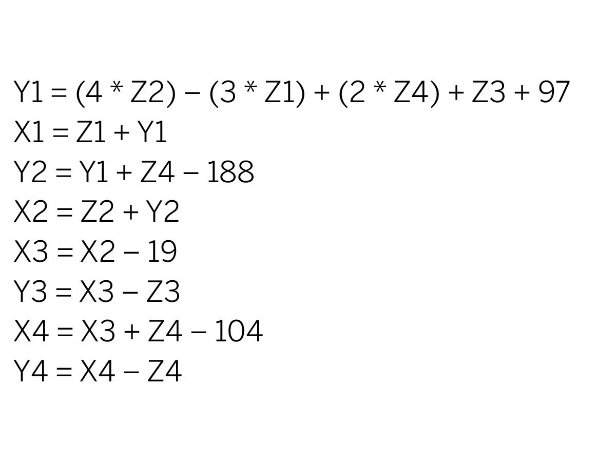

When I started programming the Bit Whacker to work the other way — encoding commands for transmission to the outlets — I found it was more complicated than simply picking byte values for X and Y that generated the right Zs. Instead, various relationships between the absolute values of the 8 encoded bytes had to be present in order for the outlet unit to accept the commands.
There’s no serious encryption going on here, but all the internal arithmetic relationships act as a parity check, making it extremely unlikely for the outlet units to be triggered by random noise or interference from other systems.
The calculations below show how this encoding works. Note that all encoding and decoding operations are single byte (mod 256), which means that the value wraps around to 0 when incremented past 255 (see picture 1).
The decoded command byte, Z3, has several possible values. Most of them correspond to buttons on the remote control, but through testing I also found several other command values which the outlet units respond to. The most notable is 0x64, which appears to affect only units that are currently off, switching them on for a brief moment and then off again.
Photo 2 lists all the commands that I was able to determine, as single byte values in 2-digit hexadecimal notation. There are commands to independently switch up to 4 units per remote, so given the number of possible identifiers, this allows 262,144 individual outlets to be controlled!
This information enabled me to encode and inject my own data to be transmitted to the outlet units. To accomplish this, I made some further modifications to the Bit Whacker firmware, so that it would generate waveforms comparable with those produced by the remote.
The final part of the project was to write a computer application in C++ to control the units, as it wasn’t very convenient having to enter commands into a serial console.
While developing my first version of the program, I found that if you called it twice in rapid succession, say, to switch multiple devices at the same time, the opening and closing of the USB port would sometimes fail. So I split the program into 2 separate processes: a server, which runs all the time in the background, holding the serial port open and managing the flow of commands; and a command-line client, which sends commands to the server.
I used TCP/IP sockets as the communication method, which lets the server and client run on different machines if desired.
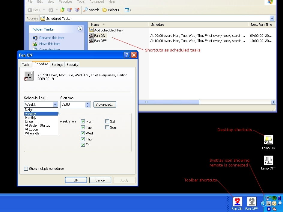
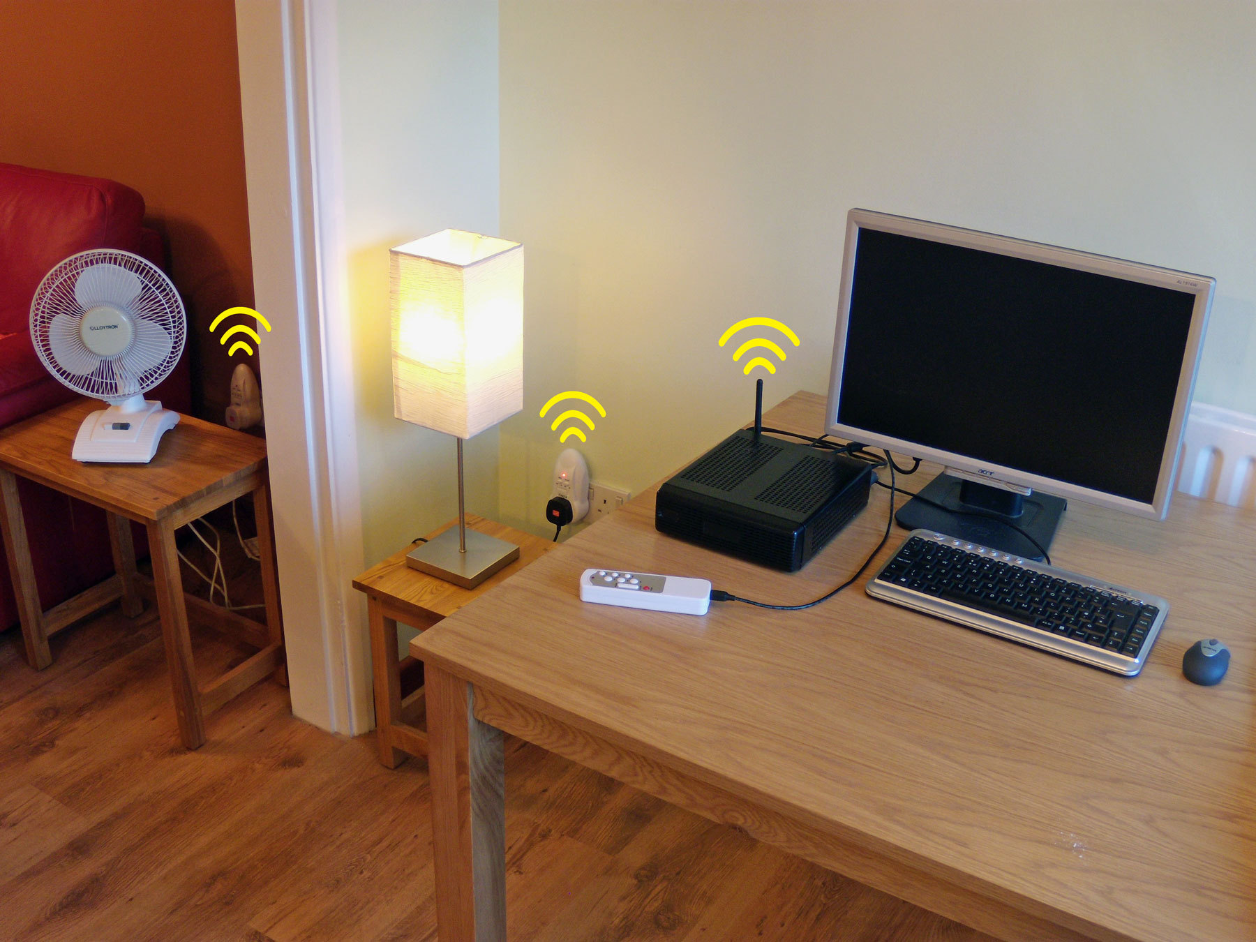
You can download the application, Remote Outlet Control here. The screen capture shows the application running on Windows. The electrical socket icon in the system tray indicates that the server process is running.
To create the toolbar at the bottom, I selected New Toolbar from the regular toolbar’s right-click menu. Then I created the Lamp shortcuts on the desktop and the Fan shortcuts on the toolbar and entered the command-line program name, outletctl, and its required arguments (device_ID [0-65535], button [a, b, c, d, all], and state [on, off]) in the Target box. I also chose an appropriate icon using the Change Icon button. (I created all of the application’s icons using Inkscape.)
For the scheduled tasks shown, I dragged the desired shortcuts into the Scheduled Tasks window, under Control Panel/Administrative Tools. This pane supports numerous scheduling options, but if it isn’t flexible enough, you can also call the program from a batch file or scripting language of your choice (I’d recommend Perl).
There’s a great deal of potential in these off- the-shelf remote outlet systems; their availability and relatively low cost makes them ideal for any electronic projects that need to switch plug-in appliances.
This project highlights just one way of using them, and I’ve tried to keep my modifications as general as possible so they’re useful to others. Hopefully I’ve shown how easy it can be to interface with these systems, and how, by understanding a bit about how they work, you can make them work the way you want them to!
This project first appeared in MAKE Volume 22, page 70.


