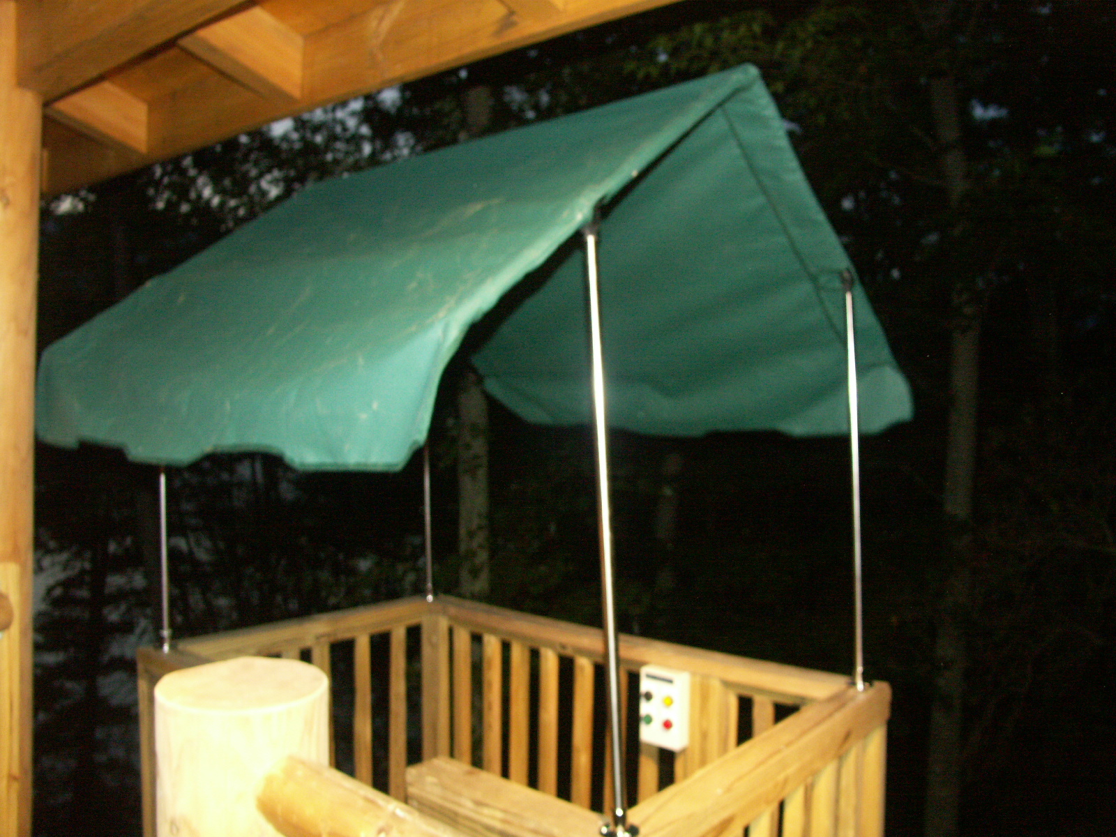
Having a house 100 vertical feet above your dock makes for a lot of steps; 10 stories, give or take. We had the house, we had the dock, and we had a lot of space in between.

Here are some YouTube videos of it in action:

Building that many steps, not to mention climbing them, was a difficult task to undertake. As my Dad and I were estimating the bill of materials needed, he suggested “Why not just build a lift?”

It seemed very implausible at the time, but as we laid out what was required, we slowly began to believe we could build it. And we eventually did.

What will the next generation of Make: look like? We’re inviting you to shape the future by investing in Make:. By becoming an investor, you help decide what’s next. The future of Make: is in your hands. Learn More.

Project Steps

Finding and clearing the path.

The first thing we did was to evaluate the area that we wanted the lift to operate in. We chose the side of the house that the dock was already on for obvious reasons, and the funicular would run from the first-level porch down to the dock area.

Next we put down the concrete we needed to hold the rail supports. For the supports close to the ground, we went with basic footers, about 10 inches deep. For the upper supports that required more height, we used 24″x24″x24″ footers to hold the 6×6 straight up. I call the top supports the “four horsemen” and the lower ones the “hurdles.”

Building Supports.

Assembling the stands was fairly straightforward. When attaching 6×6 lumber together, I highly recommend you go to a lumberyard and get some timber screws. They are quarter-inch, black, varying lengths and have either a hex cap or an inset star pattern. With a large drill to drive them, they go in like butter and hold really well. Forget lag screws; you’ll be there all day.

We chose a distance of 11 feet between supports. Since our railing was going to be 3-inch schedule 40 pipe that comes in 22-foot lengths, it seemed optimal. We also had an ME buddy run the numbers for us and he said it would work.

Note that in the red box in the first picture is a temporary set of steps. Standing on the side of a hill at a 30-degree angle is difficult to manage.

Adjustable Rail Supports.

The next part of building the rail was fabricating the holders that would support the pipe. We took 1-inch threaded rods, cut them to length, notched one end and welded on a section of angle iron.

The thought process here is that with a corresponding 1-inch nut and a washer, the height of the support can be raised/lowered with a large crescent wrench.

Mounting and Aligning Rail Supports

To hold the threaded rod, we had to drill the holes to hold the supports. Here, a 1-inch boring bit and a drill press was essential.

A spacer board was used as a template for each of the subsequent 6×6’s. When drilling large holes in pressure-treated lumber, take your time, and be sure to secure the stock so it doesn’t become a rotating deliverer of blunt-force trauma to your kidneys.

Next, we installed the threaded rod into the holes, sometimes with a 4-lb. sledge’s help. Pulling the string even more taut, we were able to line up the supports.

Instead of washers, we cut a hole into some steel plate. Perhaps a little overkill, but it made for a solid look.

When boring 1-inch holes in PT lumber, be sure to use a good boring bit and a drill press. A handheld drill will wear you out.

Building Platform for the Head Unit

The head unit is the part that does all the heavy lifting (literally). We built that out of 6×6 material with about half a yard of concrete.

The house side was attached to the existing deck, and one corner was lagged directly into the deck support post.

Track Material Selection and Placement

Next was selection of the track material. We went with 3-inch schedule 40 pipe. Our reasoning for this included:

Strength/cost ratio

Mated well to our supports

Acted as conduit to run cabling

We got a 22-foot section of 2.5″ pipe, cut it into 12-inch sections and tack-welded a 12-inch section into each of the 3-inch pipes. This allowed us to stack the pipes up the hill while providing extra support at the welds.

The tack weld left a 0.25″ gap between each section of pipe which was perfect for us to fill up with our fill welds. A little bit of grinding and the transition is near perfect, and STRONG.

Note: The drawing shows 2.5- and 2-inch pipes. This was from an earlier specification we did. We actually went with 3-inch pipe.

Head Unit

The head unit was something of our own design that incorporated two drums, each having its own cable.

A single drum with cable would have been adequate, but we went to the added expense to have two cables in case one broke or came loose. It cost an extra $200, but it was worth the peace of mind.

The drum size is 12” dia. and 15” wide with 15-1/2” dia. end plates. That means the cable will only make one layer for the complete trip. 1’ x 3.1416= 3.14’ per wrap. 4 wraps per inch, 4 x 15 = 60 x 3.14’ = 188’. The cable is ¼” galvanized aircraft cable, 7 x 19 strands, and 7000-pound rated. It runs about $1.00 per foot and there was a 15% discount for buying 300 feet or more.

The drum assembly fit on welded I-beams with pillow block bearings. The drums were on a 1.25″ rod that was coupled (via couplings) to our gear/motor assembly.

The gear assembly was a 2:1 90-degree reduction gearset. It was driven by a variable-frequency drive (VFD) motor. This gave us speed control.

Building the Cart.

The cart was built out of standard pressure-treated lumber.

I designed it such that the back third of the “flat part” (where your feet go) is actually angled to get you lower to the track.

The thought here was a bench would be installed there, so the angled encroachment would never be noticed. Besides, a lower center of gravity makes for a more stable platform.

Control System

The system we used to control the motor assembly was a 3-phase motor controller. I would list the model, but it was a model they don’t make anymore. This controller allows us the ability to ramp up speed, ramp down speed, and all the other bells and whistles we needed.

We needed an upper and lower control unit. This way, you could “call” the cart no matter where it was on the track. Who wants to scream up top to get someone to send it down?

In the diagram, the larger box is the “upper” unit, and the smaller is the “lower” unit. Each has an emergency shutoff switch.

Cart interface to Control Box

One of the tricks was how to interface the commands from the cart to the control box. To do this we bought a 4-button remote control switch system by Linear Systems. You can see the receiver unit on top of the control box. It was an outstanding unit, with a 300-foot range.

My brother wired it into a waterproof enclosure with more usable buttons, as seen in the image. The box shown in the image was the original remote. We have since built a second handheld enclosure with a matching remote so we could add an additional button for the basement level (which is for a future project). The old box is still useful though. I use it when performing cart maintenance. When on the ground, having the 2nd remote is a great resource to jog the cart up or down as I need to.

One word of caution though. I found that when I open up the enclosure to change the batteries, sometimes a button can get pushed, so I have a note inside (in black sharpie) to remind myself to turn off the tram system when changing batteries. There’s nothing worse than sitting in the kitchen changing batteries and hearing the tram come on when I’m not there to see what I did!

Wiring RTS Switches.

The Ramp To Stop (RTS) switch is what tells the motor controller to slow down to a stop. It is basically a 24-volt loop that leaves the control box, goes to RTS1, then down the pipe to the bottom, then to RTS2 and then back to the pipe and into the control box.

RTS1 is the top switch, and RTS2 is the bottom switch. Even though they are different switches, they still only control one input. So whenever the system sees the RTS signal, it will ramp down the speed based on the DEC parameter of the motor controller. I have set for 12 seconds, but I can change it if needed.

Note: The switches in the pictures have spring arms that rotate in either direction, but they only activate in one direction. Otherwise the system would stop the cart going either way. One issue I have sometimes is the top RTS switch flings back so hard, it breaks the circuit and the cart stops 8 feet later. So I have to adjust that arm down a bit to account for that.

Connecting the Cart to Cables

One would think that connecting the cart to the cables would be a simple affair, but I found that placement of the cable on the drums affected the tension, so one side or the other had slack.

One solution would be to run a continious loop around a pulley. But that would totally defeat my 2-cable backup solution, because if either piece broke, the cart and its riders would have a deathly ride down to the bottom.

What I did, and it is probably hard to see from the photo, is to have each cable locked in to a section of the cart. A secondary 8-foot section of cable was attached higher up on each of these cables and run through a pulley. This equalized the tension and solved the problem.

Adding the springs to the pulleys made the ride a little softer.

Where to go for help?

For those of you who linked here from my YouTube video and are unaware of hackerspaces, you really should investigate whether your town has one. They are an excellent resource for parts, suggestions and technical advice. I am a member of LVL1 of Louisville.

Hackerspaces are an open environment, so they will welcome you and your tram project with open arms. And you probably have a thing or two to offer your local hackerspace as well!

Look here to see if your town has one.

Future Work

There are some additional things I need to do on this thing to make it complete. These include:

Counterweight system. I want to add a counterweight so I can set the configuration to run at full speed. Right now it is at 60% speed. A CW is needed to reduce the power input requirements as well as the amount of current that needs to be dumped. Going downhill produces a lot of back-current that I have to run through a huge power resistor.

Additional Controls and Stop. The current system works, but it is possible to screw up the system. If you are at the top and press “house” it will go up!!! Fortunately I have an idiot switch at the top (see pic) that shuts the system down. Otherwise it would tear itself apart. I also want to add a stop for the basement level, and to do this will require some knowledge of where the cart is. Look for an Arduino control in its future.

If I do any of these, I will create a separate guide on the update.

Conclusion

This project and others like it are custom-designed for each location. Please use my experience as a guide to how I did it, not how you should do it. These things are VERY dangerous and should be done by professionals.