
Photography by Hep Svadja
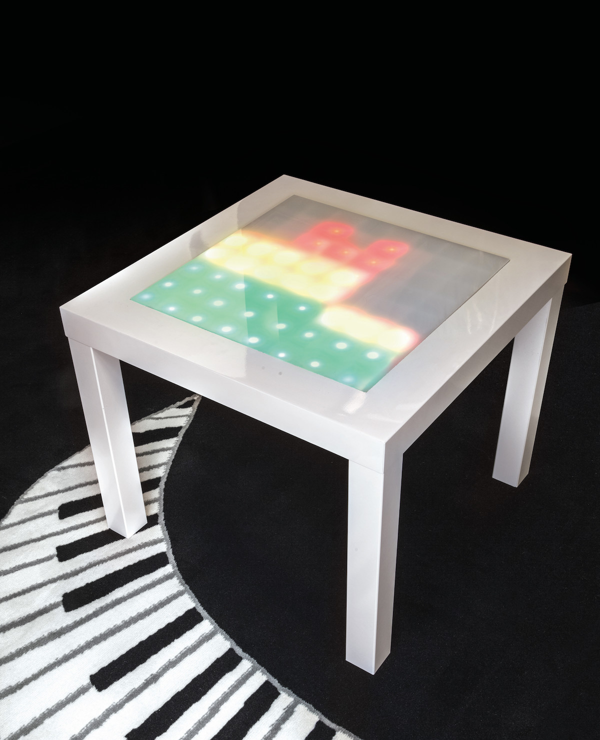
Here’s a table I bought from Ikea and inserted loads of LEDs, electronics, and a microphone into, so I can put it next to the stereo and have a display that reacts and “dances” to the music played. It’s great for parties, and it makes a superb conversation piece. It’s got an Arduino for a brain and uses a minimal amount of current, so you can run it off an iPad charger or any USB port that’s handy.
Plug it in and watch each column of LEDs jump to the bass, midrange, and treble frequencies like a jumbo-sized graphic equalizer or spectrum analyzer. I based it on the Tiny Music Visualizer project from Adafruit, using their I2C multiplexer board for a tiny 8×8 bicolor LED matrix. The Arduino code is from there, the circuit is from there — all I really created was a big handmade LED matrix, and put it into an Ikea table!
I did troubleshoot a couple of glitches for you — I found that if I connected the circuit as described by Adafruit, with a common ground for the microphone and the display, the results were erratic. If you connect the circuit as I’ll show here, using separate grounds on the Arduino board, it works fine. I also found that Chinese Arduino Nano clones did not run the code properly. Switching to the full-sized Uno solved this problem.
Build Your Own Music Visualizer Table
1. Modify the table
Start with an Ikea Lack table, about $10. The matte white was on sale, so that’s what I used. Draw a square in the center of the tabletop (Figure A) — mine was 16″×16″ (40cm×40cm), giving me room for an 8×8 matrix of 2″ (5cm) square sections.

Figure A
Carefully cut out the square from the tabletop and set it aside (Figures B and C).

Figure B
TIP: First drill a hole inside one corner of your square, or make a preliminary cut on your line using a Dremel. Then carefully cut the whole square out with a small handsaw, utility knife, or Dremel.

Figure C
Remove the corresponding 16″×16″ square of honeycomb cardboard inside the table and discard (Figure D). This will create a space about 1-11/16″ deep for installing the electronics.

Figure D
2. Mount the LEDs
You’ll use your tabletop cutout as the mounting board for your LEDs. First, mark the big square off into 64 little 2″ squares, in an 8×8 grid (Figure E).

Figure E
In each square, mark and drill holes for 2 LEDs: one green, and one red. Put them pretty close together so their colors will blend nicely to amber when they’re both lit. To speed up marking, you can make a little template from a scrap of cardboard or hardboard. I placed green toward the upper left and red toward the lower right (Figures F and G).

Figure F

Figure G
Fill the holes with the LEDs — 64 red and 64 green — inserting them from the back so they emerge on the white top (Figures H and I). Take a picture with all the LEDs in place. Feel good about what you’ve done.

Figure H

Figure I
3. Wire up your LED matrix
You’re just making a very large version of the common cathode matrix shown in the wiring diagram (Figure J). The numbers here indicate which pins you’ll connect to on the Adafruit LED controller board.

Figure J
First, cut some wires and strip them, lots of them — I suggest you buy a good wire stripper, I did and it made it so much easier! Once you think you’ve got enough, cut some more: You’ll need 56 black, 56 red, and 56 green wires. Each should be about 3″ (7cm–8cm) long (Figure K), but this will vary depending on your array, so just check before you cut all of them.

Figure K
Next, to save my fat fingers whilst soldering, I twisted the wires into chains of 7 — end to end — so I could solder them easily without trying to hold multiple wires at once (Figure L).

Figure L
On the back of the LED board, bend the legs of each pair of LEDs so that their cathodes touch, but their anodes are separate. Solder all the cathodes together using the black wires (Figure M), following the wiring diagram.

Figure M
Solder all the anodes of the red LEDs together using the red wires. Then solder all the anodes of the green LEDs together using the green wires (Figure N). Finally, cut and solder 24 wires, one to the end of each row and column. These will run off-board to connect to the electronics (Adafruit board, breadboard, and Arduino) so their lengths will vary. It’s easiest to locate the electronics near the bottom edge of your LED panel (the front of the table) but you could choose another location, just make sure these off-board wires are long enough to reach.

Figure N
TIP: You could use red for all the anodes, but we found using red and green here makes the connections a lot easier to follow later. —Jenny Ching, Make: Labs
4. Connect the electronics
Connect your newly created LED array to the Adafruit Bicolor LED “backpack” board by soldering its 24 wires directly to the top of the circuit board, following the wire numbering from the LED wiring diagram (Figure J) you used in the previous step. As shown here in Figure O, the backpack board’s pin numbers run clockwise from 1 at top right to 24 at top left.

Figure O
Now plug the microphone and the LED backpack board into your breadboard and use jumper wires to connect the Arduino as shown in Figures P and Q.

Figure P

Figure Q
NOTE: I’ve mainly used the circuit diagram from Adafruit, but I’ve made one change: The GND wire from the microphone goes to a different GND connection than the LED array. I found that if I used the same common GND for both, the microphone output was corrupted and the display behaved erratically and didn’t respond to music at all. If you use 2 different GND pins on the Arduino Uno, everything works fine.
5. Program the Arduino
Download the Adafruit_LED_Backpack library and put it in your Arduino/libraries folder. Download the project code, and move the ffft folder to your libraries folder too.
Open the sketch Piccolo.pde in the Arduino IDE on your computer, then upload it to your Arduino board. Test the matrix and circuit by playing some music (Figure R). You should see the columns of LEDs jumping and dancing to the sound!

Figure R
6. Build the matrix grid
Cut 18 strips of hardboard or cardboard approximately 15½” long and 1⅛” wide. This width is based on the depth of the table, so test-fit your LED panel and electronics into the table before deciding how wide to cut your strips.
On 14 of the strips, use a saw to cut intersection slots every 2″, to half the depth of your strip (Figure S).

Figure S
For high reflectivity, I used some white laminated hardboard I found in the garage. Then I used the kids’ “gloopy glue” (PVA white glue!) to stick reflective photo paper to the back of the hardboard, and cut it to size with a craft knife once dry. (It’s probably easier to just paint everything white.)
Now assemble the grid and hot-glue the strips in place (Figure T).

Figure T
7. Complete the table
Get a piece of plexiglass (perspex) the same size as your matrix. I covered mine in frosted window film, but if you can find translucent or frosted plexi in the first place, it will save you some effort. For added diffusion, I used some baking parchment paper as well.
Cut a little hole in the bottom of the table to allow a USB cable to fit through (Figure U). Hollow out a pocket in the honeycomb cardboard to house your electronics.

Figure U
Now slide the electronics into place (Figure V). You can leave the microphone inside, or mount it poking out of the table someplace you like. When it’s all aligned to your satisfaction, you can tack the grid down to the LED panel with a few blobs of hot glue (Figure W).

Figure V

Figure W
Finally, glue the plastic top in place. I used a hot glue gun, and squeezed a thin bead between the acrylic and the tabletop (Figure X). It’s not substantial, but it keeps everything situated.

Figure X
Your table is now complete!
Get This Party Started
You and your Music Visualizer Table are ready to party. Plug its USB cable into a phone charger or any USB port, then crank up the tunes and enjoy watching the giant tricolor pixels dance like splashing fountains of spectrum analyzer goodness!
How It Works
Audio Analysis and Graphics
The microphone you’re using has a built-in op-amp that provides a nice clean amplified signal. The Arduino code reads the mic input on Analog pin 0 about 9,600 times per second (9.6kHz) and performs some fancy math called a fast Fourier transform (FFT) to convert the raw audio samples into a frequency spectrum. Additional fancy math is performed to split this spectrum into 8 separate frequency bands and analyze the intensity level of each band.
Each of the 8 levels is then rendered graphically from 1 to 8 pixels high — low levels are green, medium are yellow, and high are red. These pixels are redrawn zillions of times a second and sent to the LED board. It even does that cool trick where the peak pixel hangs for an instant before falling back down (we love that!).
If your mic’s not picking up enough sound to really rock the LEDs, try mounting it in a more exposed location. (Or just turn the music up!)
LED Multiplexing
Adafruit’s Bi-Color 8×8 LED matrix “backpack” board is designed to drive their colorful little 2-inch 8×8 pixel matrix (Figure Y) that has 64 red and 64 green LEDs inside, for a total of 128 LEDs controlled as an 8×16 matrix (2 LEDs per pixel). In the Music Visualizer Table, you’re simply substituting a bigger, homemade LED matrix that’s laid out exactly the same way.

Figure Y. Photo courtesy of Adafruit
Like most LED displays, this one is “multiplexed” to save wiring — rather than connecting each LED to a microcontroller individually (129 wires!), they’re connected to each other in a grid of columns and rows, controlled by just 24 wires. When the microcontroller passes voltage through the correct column and row, an individual LED lights up. Efficient!
I2C Communications
But 24 is still a lot of pins — more than your Arduino board has to spare. The Adafruit multiplexer board solves that problem by using a dedicated LED controller chip to drive all the LEDs. All the Arduino has to do is write data to that chip using the 2-wire I2C serial communication interface, a common protocol designed to let one chip talk to another. The Arduino Uno can easily communicate with I2C devices using its dedicated pins for I2C clock signal (SCL) and I2C data (SDA), shown below. For older Arduino boards, just use analog pins 5 and 4. Now you’re controlling 128 LEDs using just 2 pins on your Arduino.
Adafruit wrote a basic Arduino library for handling the LED multiplexer board. It can be adapted to any I2C-capable microcontroller — just check yours to see which pins it uses for I2C communications.
Going Further
You can easily program your own custom graphics and animations to run on your LED table anytime — just install Adafruit’s GFX Arduino library.
Before I started this project, I really wanted to build a Tetris table. How would you go about creating something like that?
Would this be a little cleaner using difused common cathode Red/Green Leds? Great write up!
Some rookie questions: 1) can you be more specific (link would help) re: the Microcontroller board? 2) what gauge wire do you recommend for hooking up the LEDs? 3) 5mm LEDs good? thanks!
Would the Uno R3 work? (https://www.adafruit.com/products/50)
I have completed this project but the green LEDs are vary faint like there are being under powered i am using 3v green LEDs. the red seems to be working just fine. is there a way to give the greens more power?
Hey Kevin, I´ve the same problem. Did you solve that? If you did it… How did you solve the problem? I´m getting crazy with this and I need a solution, It´s my class project.
Thanks!!
unfortunately i was not able to solve the problem with the LEDs i used in my construction, but i think that if i had built the project with a green LED that had a slightly lower voltage so that it would get over powered slightly that it would have worked better, seemed to me that because the red LEDs that i used had a range of optimal power that started lower than the green they were more visible, hope this helps
if you get the room really really dark you can see the green ;)
Thanks for the reply! I´ll try to solve it with my project teacher, I need a solution haha. The class will be illuminated, so I can´t apply your solution! haha.
Can I use the prongs that came with the Adafruit gear instead of jumper wires? I bought a Kuman set and
it only came with around 30 jumper wires. Is there an alternative to the jumper wires or are those the only things i could use?
I have a couple of questions, firstly what diameter and make of LED’s would you recommend. What type/gauge of wires would you recommend for wiring the LED’s.
Does anyone have a part list for this build?
hey! the parts list is at the top of the page in a righthand sidebar
ConfigureACCEPT
Privacy Overview
Necessary cookies are absolutely essential for the website to function properly. This category only includes cookies that ensures basic functionalities and security features of the website. These cookies do not store any personal information.
Any cookies that may not be particularly necessary for the website to function and is used specifically to collect user personal data via analytics, ads, other embedded contents are termed as non-necessary cookies. It is mandatory to procure user consent prior to running these cookies on your website.