[youtube http://www.youtube.com/watch?v=psTa5ZrqAyo&w=620&h=349]
Taking your pulse is as simple as holding a finger to your neck or wrist and timing the beats with your watch. But if you want to record the data or use it to trigger events, you need to turn that mechanical pulsing action into an electrical signal. This pulse sensor fits over a fingertip and uses the amount of infrared light reflected by the blood circulating inside to do just that.
NOTE: While we think it’s pretty obvious, our lawyer just tapped us on the shoulder and asked us to emphasize that this is not a medical device. If your application is life- or health-critical, please use only an FDA-approved medical-grade pulse sensor, OK? Thanks!

Schematic with symbolic op-amp representation.
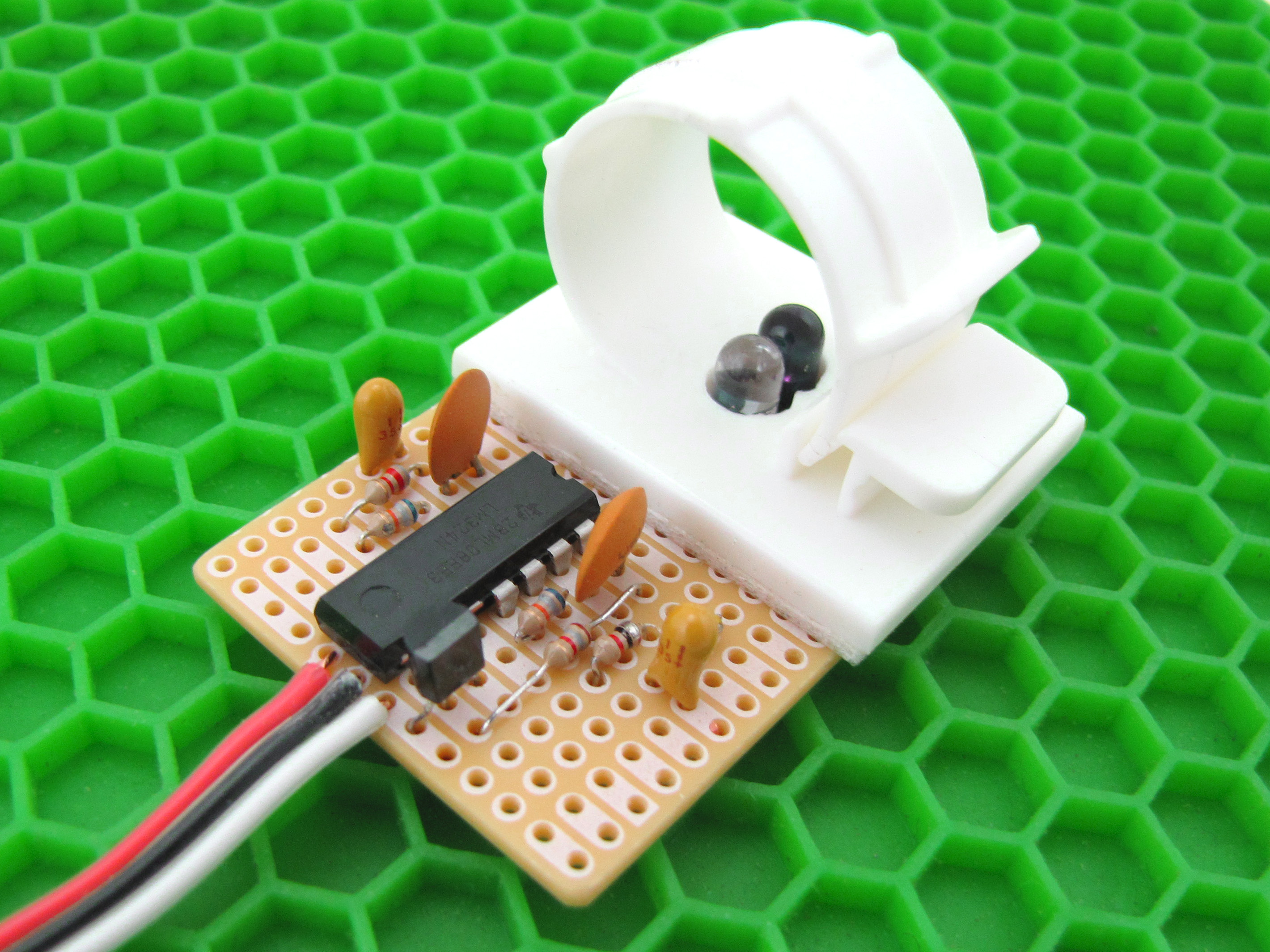
The sensor itself consists of an infrared emitter and detector mounted side-by-side and pressed closely against the skin. When the heart pumps, blood pressure rises sharply, and so does the amount of infrared light from the emitter that gets reflected back to the detector. The detector passes more current when it receives more light, which in turn causes a voltage drop to enter the amplifier circuitry. This design uses two consecutive operational amplifiers (“op-amps”) to establish a steady baseline for the signal, emphasize the peaks, and filter out noise. Both op-amps are contained in a single integrated circuit (IC or “chip”), and hooking them up is really just a matter of interconnecting the pins correctly.

Schematic with physical op-amp representation.
The two op-amps output a clean but weak signal which is amplified by the transistor before output.

Component- and solder-side views of the complete sensor, without finger cuff.
The complete pulse sensor is a three-wire device that runs on 5V and outputs signal on the white wire. You can visualize and/or record this signal in a number of ways, but we’ve chosen to connect to a personal computer through Arduino, mostly because of the ease of integrating Processing, which in turn is very handy for visualization. But you don’t really need an Arduino to use the sensor. More on that below.

Sample output in Processing.
RadioShack IR receiver seems to be a photo transistor, not a photo diode. Also, is 2N3904 really wired towards the positive supply without a pull-down to ground?
Also, doesn’t the leftmost op-amp have a feedback resistor (in parallel to the 0.1uF cap) also?
I am getting an error in Processing. I have tried to enter the correct serial port (14) the my Arduino is connected to but nothing helps. Any ideas in how to solve this?
Array Index Out Of Bounds Exception: 1
(this line is highlighted)
myPort = new Serial(this, Serial.list()[1], 9600);
This is easy to fix. You have to change the serial port acording to your computer.
In the beginning of the code they put a “println” command. So the first thing that you should see in console is the list of the ports that are avaiable.
// List available serial ports.
println(Serial.list());
So if you only have 1 port avaiable change the setup configuration
(Original)
// This line might change for different computers.
myPort = new Serial(this, Serial.list()[1], 9600);
(after the change)
myPort = new Serial(this, Serial.list()[0], 9600);
Alright, I got Processing to function properly. Now, I am having an issue with the signal itself. The values do not appear to change when a finger is place over the emitter detector pair. I did build this circuit on a breadboard. Would that be enough to alter the capacitance values? If so, would that cause the values to not change?
For some reason, I feel like the photodiode is wired backward.
Could someone conform this?
I suspected the same thing. If you place the emitter/detector ‘flat to flat’ as they describe, I’m thinking it won’t look like that on the solder side of the board.
Would it work if I connected the transistor output to my computer’s soundcard mic input and used soundcard oscilloscope? http://www.zeitnitz.de/Christian/scope_en
The thing i did to make it work is to use a trimpot of 500 Ohm in serial with a 56 Ohm resistor in stead of the 220 Ohm resistor used by the Ir diode. Now you can change de sensitivity of the pulsdetector ( amount of IR light). But I used a IR diode and detector from a old Ligitech mouse :-)
This was a great project, really enjoyed building it! I’ve got photos and details of my build here:
http://www.lungstruck.com/projects/infrared-pulse-sensor/
I used the layout presented in this article but based the circuit on the Let’s Make Robots article, so I used the LM358 Op Amp and included the trimpot among other changes. I haven’t done much with it yet except test it on an oscilloscope, but I plan to hook it up to an Arduino and have some fun at some point.
where is the arduino program to download ??
Hello B, you can find the download link to the Arduino Sketch on Step #8 Hope you have fun building and Make sure to post a link to your build in the comments !
Hello friends, I would like to know where is the arduino program to download,too. Thank you.
Hello Paulo, you can find the download link to the Arduino Sketch on Step #8 Hope you have fun building and Make sure to post a link to your build in the comments !
Can I use 2.2K Resistor instead of 1.8K resistor? Actually, I can’t get this in any of the nearby shops (Radio Shack is also not there in our country). Also, I am using 2.2 uF tantalum capacitor instead 1 uF (This one is not available,too), So how much difference it would create? And sir, this is my first project, so please give some other helpful tips too.
You can get this components here http://www.soldafria.com.br
I fixed the ‘Out of bounds Exception’ error but now getting ‘Error inside Serial.init()’.
Any help? Eager to get this one working and start modding.
1K resistor in schematic (op-amp representation) is missing at the 2nd stage of OPAMP. Please update, took me time to figure what was wrong. Great project!! Thanks
I am getting an error in Processing. I have tried to enter the correct serial port (14) the my Arduino is connected to but nothing helps. Any ideas in how to solve this?
Array Index Out Of Bounds Exception: 1
(this line is highlighted)
myPort = new Serial(this, Serial.list()[1], 9600;
I’ve changed it to myPort = new Serial(this, Serial.list()[0], 9600;
and now marks Erro inside Serial.()
change the port number to 0
can you guys share with me your processing code? mine seems to be off course, i get an error saying ” the function readstringuntil(char) does not exist”. any tips?
Hey guys I am also getting the same error “the function readStringUntil(char) does not exist” any help…..
1) Find location of the file Serial.java : sudo find / -name “Serial.java”
2) Edit the file by the command: sudo nano /Serial.java
3 Insert the missing function readStringUntil() as given in this website:
https://github.com/processing/processing/commit/d9768bca5db8dd7367c343cd396552f6afdc5c64
Thanks for the reply but man I am using Windows 8 not Linux…
Please help
when i put in the red cable into the arduino the arduino will just shut off can you one of you guys help me please
sorry wrong wording when i plug in all the wires the arduino just turns of and then i unplug the red or the black it turns right back on some one help me its a science project it due in 2 days please help me
5o3c also over heats when their all in
can i use a HC-06 bluetooth module to get the serial pulse data wireless with processing?
or any suggestions about wireless comm. ?
admin,can u give me the coding of this project…i had try to find it but i couldn`t
aiman, maybe this can help you .Take a look. http://www.instructables.com/id/Homebrew-Arduino-Pulse-Monitor-Visualize-Your-Hear/step10/The-Codes/
can i use a perma-proto 1/4 sized breadboard?
i need to this code…
can u help me?
did you get the code
if yes then please send me also
are they photo transistors ?
no, infrared photodiode and infrared LED
photo diod circuit
I’m new to electronics and I’ve make the circuit in a breadboard, check it a lot of times, but it doesn’t work. It’s almost no difference if I put my finger or not. If I use a torch to light the detector, values grow up a little, so it’s reacting.
My circuit has 2 differences with this, first resistors are 1/4W and the emitter LED is clear instead of blue.
Any idea what can be wrong?
In the Schematic there are only five Resistors besides the 2 resistors for the emitter and detector and in the Photo there are 6 Resistors on the upper side? Is that a fault in the schematic with the physical op amp representation? The Sensor works not for me -.-
Thanks for help ahead
Hi make a doble check in the schematic are 7 resistors, in the Photo are 5 resistors and in the Other side aré 2 resistors (for the ir emiter and receiver)
I MAKE it, but i changed the 39K resistor for a 10k, and put the 1k resistor fom pin 13 to ground
Any chance to get in contact with you? I really need help on this one… Any answer is really appreciated
Sure my e-mail: Jose_ale_perez@hot….
Jose, te envie un msj al hotmail, espero me puedas ayudar. gracias.
Where is the codes?
Hi, i try to make this circuit and it dont work i use the same components and anythig happens help me please
There’s an error of omission in the 2nd wiring diagram above. The one labeled “Schematic with physical op-amp representation.”
The 1K resistor going from pin 13 to ground isn’t shown in it. Don’t spend all day dumbfounded like I did. Put it in there.
The module in the pictures couldn’t possibly have worked. The IR Detector is wired up backwards. Since the emitter & detector are positioned flat to flat (cathode to cathode), the pictures show the anode being soldered straight to ground, so there would never be any voltage drop from it.
Frankly, this thing doesn’t even work very well once you get it assembled correctly. Either the emitter doesn’t put out enough power, the detector isn’t sensitive enough, or both. It’s possible that the issue could be my fingers (calloused w/ somewhat poor circulation), but a good design would be able to handle that.
I think that this circuit could work if you replace the IR setup with a bright LED & a light dependent resistor. I believe that’s how the professional ones are designed. The more light the better.
I’d be interested to hear if anyone has actually made this work as it’s shown here. I mostly just found it frustrating and a waste of money. =
Actually, it works very good, i just changed the emitter for an ultrabright red LED, and the detector for a light dependan resistor(LDR). And for the emitter detector combo i make a little black box and i put the emitter on the top of the finger and the detector on the bottom. Knowing that it’s only matter of placing your finger correctly
plz give me ppt for this project
So did this circuit work for anyone after connecting IR photodiode in reverse biased condition?
Is 220 ohm or 220K ohm?
just 220 omh
SIr ,
Can you give me coding of this project ..
I MAKE it, but i changed the 39K resistor for a 10k, and put the 1k resistor fom pin 13 to ground
Hi, I have the same setup as yours. But I can’t receive significant voltage drop in my IOIO board. I am trying to figure out what goes wrong.
What is the voltage reading output from the transistor? What is the input go into the pin 3 of the LM324?
I used the same configuration as shown, for the 324, i think that the voltage drop is not significant for a multimeter, but the sampling in the arduino is significant! use an oscilloscope or plug it directly to the arduino input and test it, my voltage drop was not significant either
I am using the IOIO-OTG board. According to the documentation, arduino maps 0-5V to 0-1023. So what is the output voltage after the transistor for you? Mine is something like mV.
These are the voltage readings from the input pin on IOIO board.
pulse:0.28709677
pulse:0.28709677
pulse:0.27419356
pulse:0.27419356
From the IOIO board voltage reading, I have around 2.3-2.9V after the first 1uF capacitor. I have 3.3V after the first op-amp after the 0.1uF capacitor before second 1uF capacitor. After the 1uF capacitor, I got 0V most times, but sometime 2.3V. After the second op-amp, I got something like 0.03-0.08V.
Any idea?
I guess something wrong with the circuit.
Try to use another sensor and emitter, I used the ones from sparkfun, change the IC 324, the variant i noticed was between 750 and 725 from the A/D.
I have IOIO board, so I need to convert the output voltage to 1~1024.
pulseVal = (float) (pulse_.getVoltage()/4.8*1024);
I got somethings look like a pulse finally, but have to use super bright LED. Maybe the IR LED is too weak.
I will order some other component to try it out.
Jose, could you please share some clear pictures with us?
ok it was a great signal! Tomorrow i will! i just arrive from work! good night!
There , notice the 10k resistor on the receptor and the 1k resistor from pin 13 to gnd soldered behind.
the three holes to the left, up> +5Vdc, middle> GND, down> Signal, the four holes to the right, up> ir sensor down>ir emitter
Hi, can you explain how did you get the pulse to work? my processing screen is blank and it doesnt show any pulses. Please help me. Thank you.
Hi, with LM324DG work? or LM324N/DIV ??? Can you please show final scheme that works perfectly? I ask this because I understand that missing components of the scheme. I want to use this circuit with a board arduino uno and labview (with lifa base). thanks!
i used LM324N, send me your e mail, ill send you all my examples an work…
petry_assassinu_2007@yahoo.com thank you
Hello, I am still waiting to receive your mail with the final and operational scheme of the sensor. Please send mail please? petry_assassinu_2007@yahoo.com
Thanks!
Hi Jose,
I had a ques regarding this prototype, i need my signal to be pure like heart signal, with all the QTSR intervals, however the signal shown in this project the signal shown is just like a square wave n rarely looks like heart signal, n has lots of noises..i am not planning to connect it to arduino, as i am planning to have it connected to MATLAB and simulink for processing…can u help in that matter, how to have a heart like signal? i really appreciate it.
my email is:
v.f23171@gmail.com
Nice, but there is some troubles with the sensor and receptor, it must be separated by something white
Hola, por algo blanco te refieres a cualquier cosa? por ejemplo un papel? Yo también tengo problemas para hacer funcionar el circuito, pero no se si el problema que tengo es el mismo que tu tuviste. Saludos