This guide will teach you how to build and program your own accelerometer controlled maze game. It does assume a basic knowledge of soldering, breadboards, and programming in Arduino. by the end of this guide you should be able to make your own maze by editing the code and then solve it by tilting your game to move the ball. The program itself is fairly complicated but fully commented and the main components of it are described in this guide.

Project Steps

Assembling Your Game

Create your breadboard-arduino setup

Cut a piece of cardboard or pre-holed 1/8″ MDF that is 3″ x 4″

Cut two 2″ long strips of foam tape and put one on each corner of the bottom of your breadboard. Press your breadboard on to one side of the cardboard/MDF rectangle as shown.

Do the same for your Arduino or thread two or three 1/4-20 screws and corresponding nuts through your pre-holed board (or poke holes in your cardboard using a pencil or similar) and the mounting holes on the Arduino

Solder the header pins on to your Nokia LCD screen. A step by step guide can be found here: http://ladyada.net/products/nokia5110/

Take a strip of masking tape (approximately 4″) and wrap it into a loop with the sticky side facing out. Place the loop against the back of your screen and then replace it on your board. Make sure the screen is as far to the left as possible.

Wiring Your Game

Wire your screen up with your logic level shifter chip (included in the Adafruit package). A guide can be found here: http://ladyada.net/products/nokia5110/ The next step in this guide also has a series of step by step pictures for the complete wiring of the game.

Make sure that both your LCD and your logic level shifter chip are as far to the left of your board as possible, as shown in the picture. Otherwise you may not have room for the accelerometer.

Add your accelerometer to your board. Take care to orient the accelerometer such that the +5V/Xout side point toward the top of the screen. Otherwise the directions that the ball moves when the game is tilted will be wrong. A complete wiring guide can be found here: http://arduino.cc/en/Tutorial/Memsic2125…

A diagram of my breadboard can be seen to the left. It also includes all the wire color conventions which I used which may make reading the other steps in this tutorial easier. This diagram and the wiring schematic were made using Fritzing.

Wiring Step-By-Step

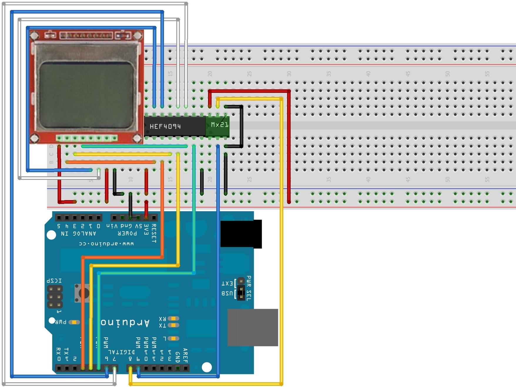
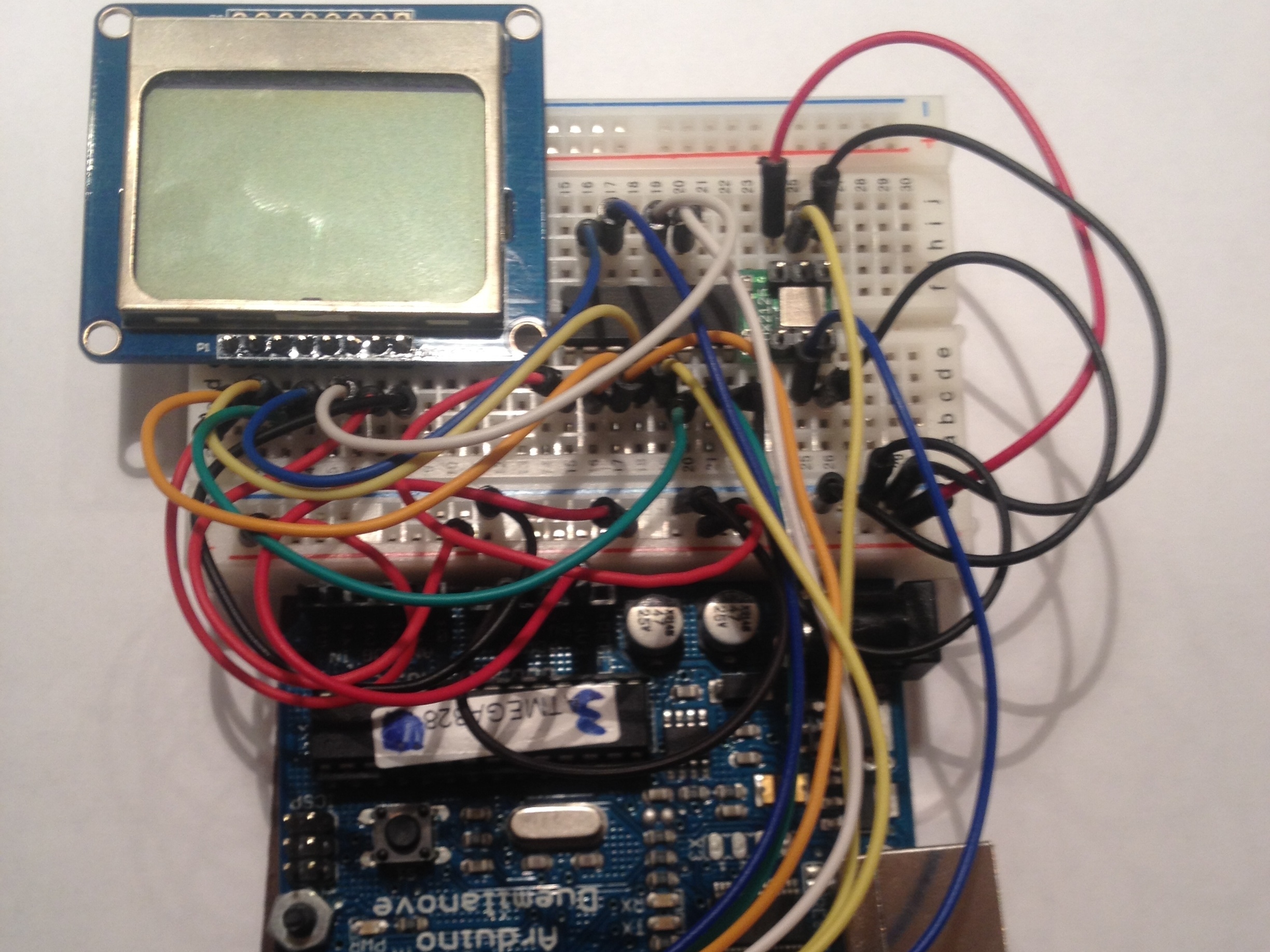
First wire the LCD to the logic level shifter chip, power, and ground, as shown in the first picture.

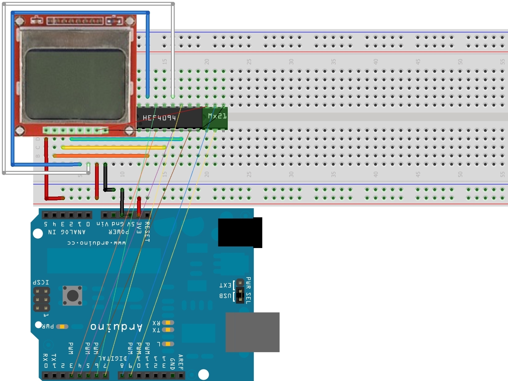
Then wire the logic level shifter chip to the Arduino. This can be seen in picture two and completes the connections necessary for the LCD screen.

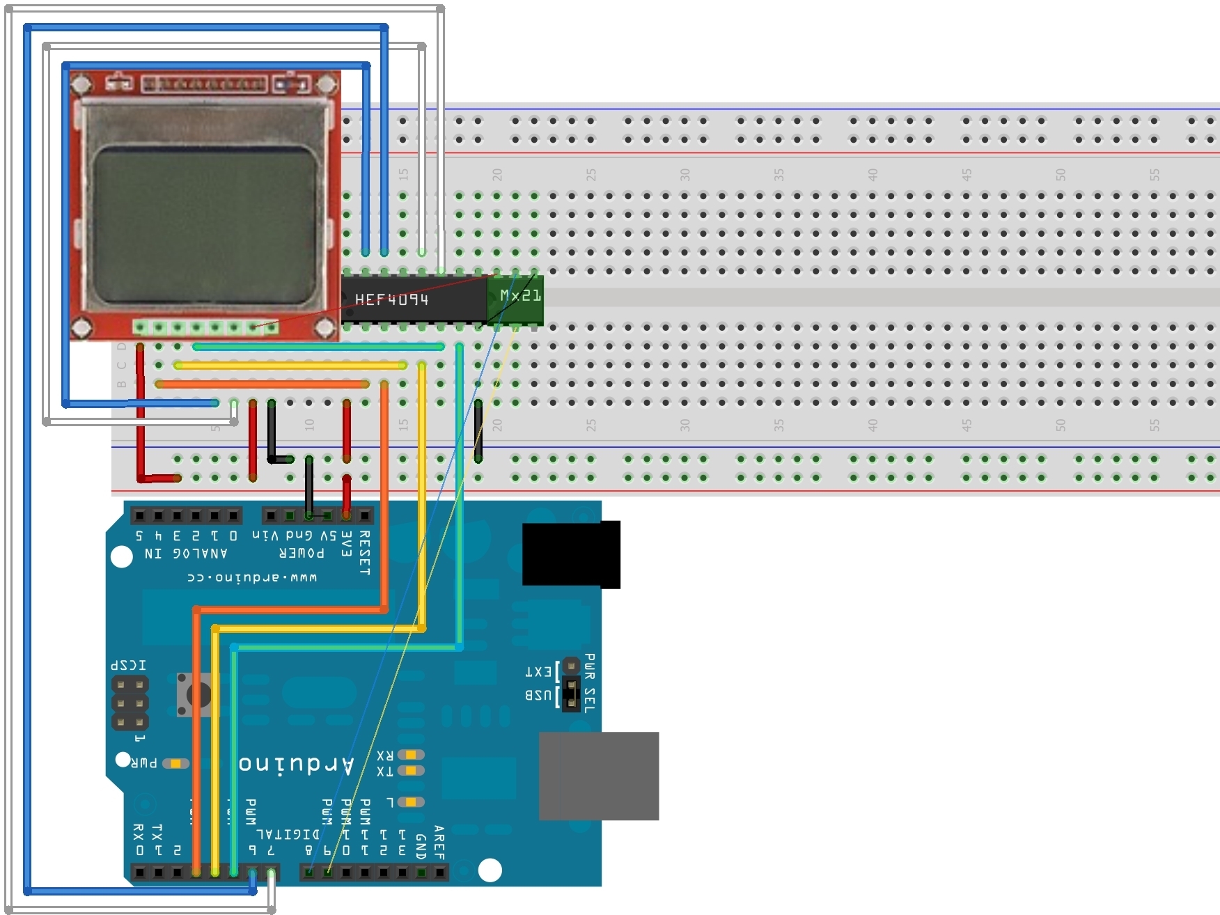
Finally you will need to connect the accelerometer to the Arduino, power, and ground. These connections are diagrammed in the third picture.

Setting Up Your Program

Install the latest version of Arduino if you have not already. The installation link can be found here: http://arduino.cc/en/Main/Software

Install the PCD8544 library and GFX library found in the Adafruit how-to link for the LCD screen (previously listed under the “Assembling Your Game” step). The links for download are under the “Testing” heading.

To install a library first download it from the internet. Then, after extracting the files from the .zip file you downloaded, drag and drop the library of unzipped files into the “library” folder. This is found in the software folder for Arduino. A complete guide from Adafruit can be found here: http://www.ladyada.net/library/arduino/l…

The getPixel command in the original PCD8544 library does not work correctly, for this reason you will need to open the and make the edit pictured here. I opened it in atmel studio (found for free here: http://www.atmel.com/tools/ATMELSTUDIO.a… ) which makes it a lot easier to figure out what’s what.

Under the heading that says “else”, indicated by the yellow box, comment out the existing code, shown in the red box, and type in the updated code found in the green box.

Inserting The Code

Now that you have everything set up you’re ready to upload the code to your Arduino! You can get the code here: https://docs.google.com/document/d/1_p4r…

To get it on your Arduino:

Open the Arduino software on your computer.

Click on the “new” button which sits directly to the right of the upload button.

Copy and paste the entire code found in the link above into this sketch.

Save the program naming it whatever you want. I recommend a name that describes the program accurately so that it is easier to identify when you want to find it later. For example, I named mine Maze_Game_V2 since it is the second version of my program for my maze game

Plug in your Arduino, select the correct Arduino model and serial port (under Tools/Board and Tools/Serial Port respectively) and click the upload icon.

How The Code Works

The ball is moved around by mapping the tilting of the screen to a certain range of speeds (in this case from 0 to 3 pixels per loop through the program). In the code the maximum speed is set to the radius of the ball so as to stop the ball from jumping through the walls when it is at top speed.

A maximum speed in any direction is set using a series of if statements which limit the maximum and minimum values which the Arduino will read from the accelerometer.

Stopping the ball from going off the screen is controlled by a series of if statements which limit the maximum and minimum positions of the ball on the screen.

Collision detection is performed by a group of if statements which check four separate subroutines (located under the main program loop).

Each of these subroutines checks a line of pixels running from the outermost pixel of the ball to the center of the ball.

These lines run top-center, bottom-center, right side-center, and left side-center. Every pixel in each line is checked so that even if the ball is moving fast enough that its velocity will carry its outermost pixel into a wall the other pixels in the check line will recognize that the ball is going into the wall and stop it.

Great care was taken so that the size of the ball can be changed by editing a single variable (RAD) and all other attributes of the program will remain the same. The program will work with walls of any thickness.
Making Your Own Maze

The massive bitmap array at the beginning of the code is the maze itself. If you look closely you’ll see that the 1s, which make black pixels, are organized in the same way as the walls of the maze. The array is acually 88 pixels wide even though the screen is advertised as being 84 pixels wide because my screen had four more usable pixels.

You can edit the maze by changing which pixels are zeros and ones and therefore change which are black and white.

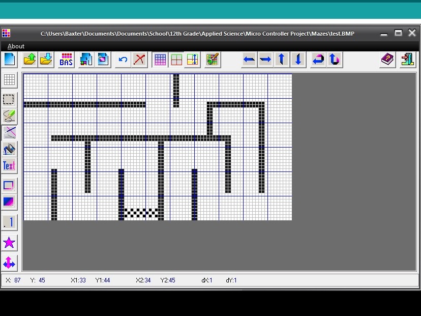
I am sorry that this is a very time consuming and clunky way to make new mazes. To ease the design process at least you can download the FastLCD program (which unfortunately only works on PCs) here: http://www.amontec.com/lcd_nokia_3310.sh…

FastLCD is designed to generate bitmaps which could be used in your existing code in place of the binary array however I have not been able to get this to work yet.

You can also check to make sure the LCD is reading your maze correctly using the getPixel command by un-commenting the serial_print_bitmap line (located in the blue box in the picture). Open the serial monitor (ctrl+shift+m) while the program is running to view the maze as the program reads it.

The program will start reading it from the begining again once it reaches the end. For this reason click the “auto scroll” box at the bottom of the serial monitor once the maze has been displayed once,

Activating this line will knock out any screen movement but it is a really good way to make sure that your edit to the getPixel command is correct and also an interesting exercise in watching your code work.

Play Your Game!

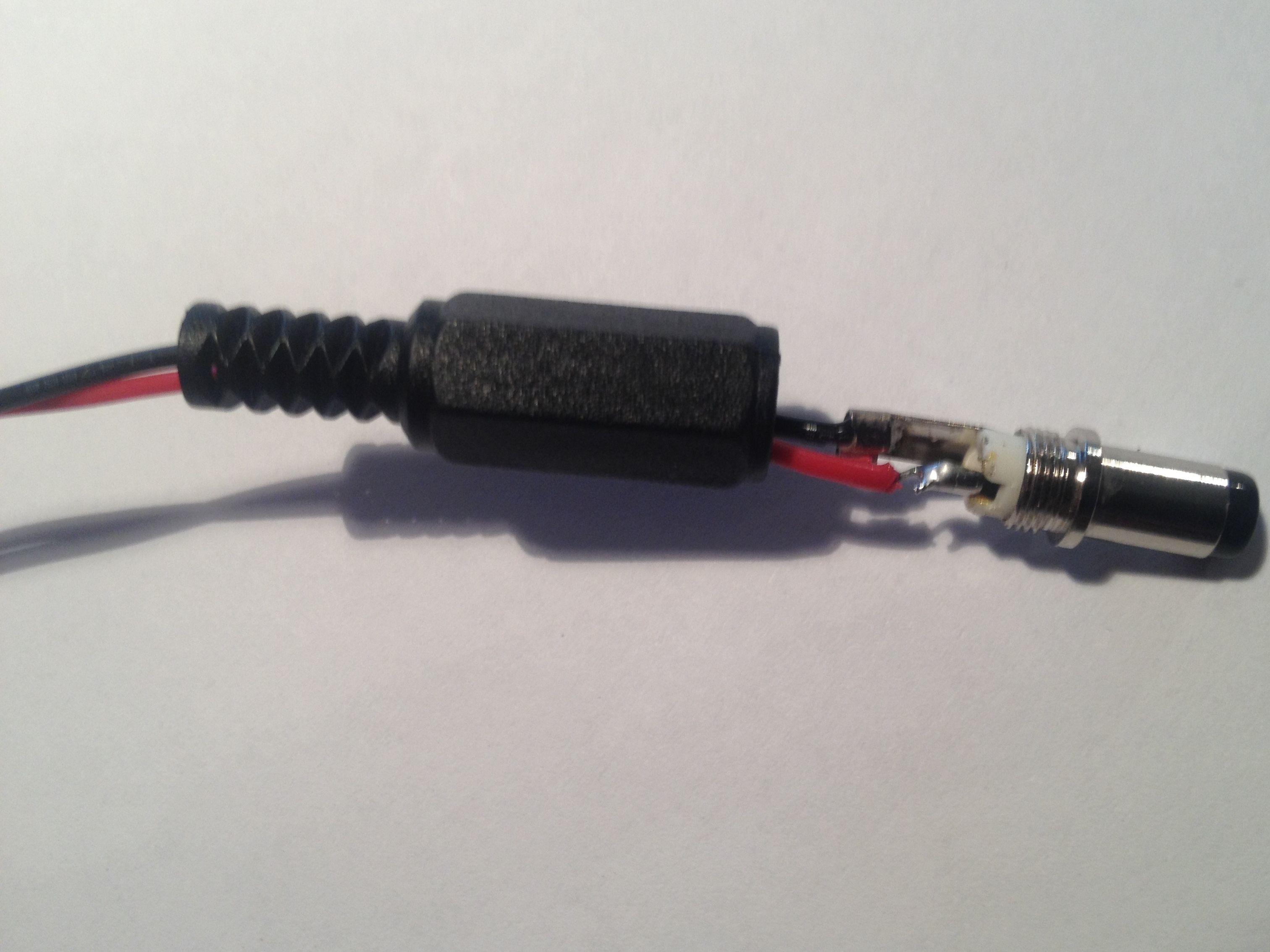
You can now solder your Arduino power plug to the leads of your 9V battery case to make your came more mobile. Use the picture to the left as a guide for which tab the red and black wires connect to.

You can also tape the battery pack to your cardboard/MDF back plate using a strip of masking tape (approximately 5″ long) to make the game a little more handheld.

Enjoy your custom handheld game and show it off to friends!