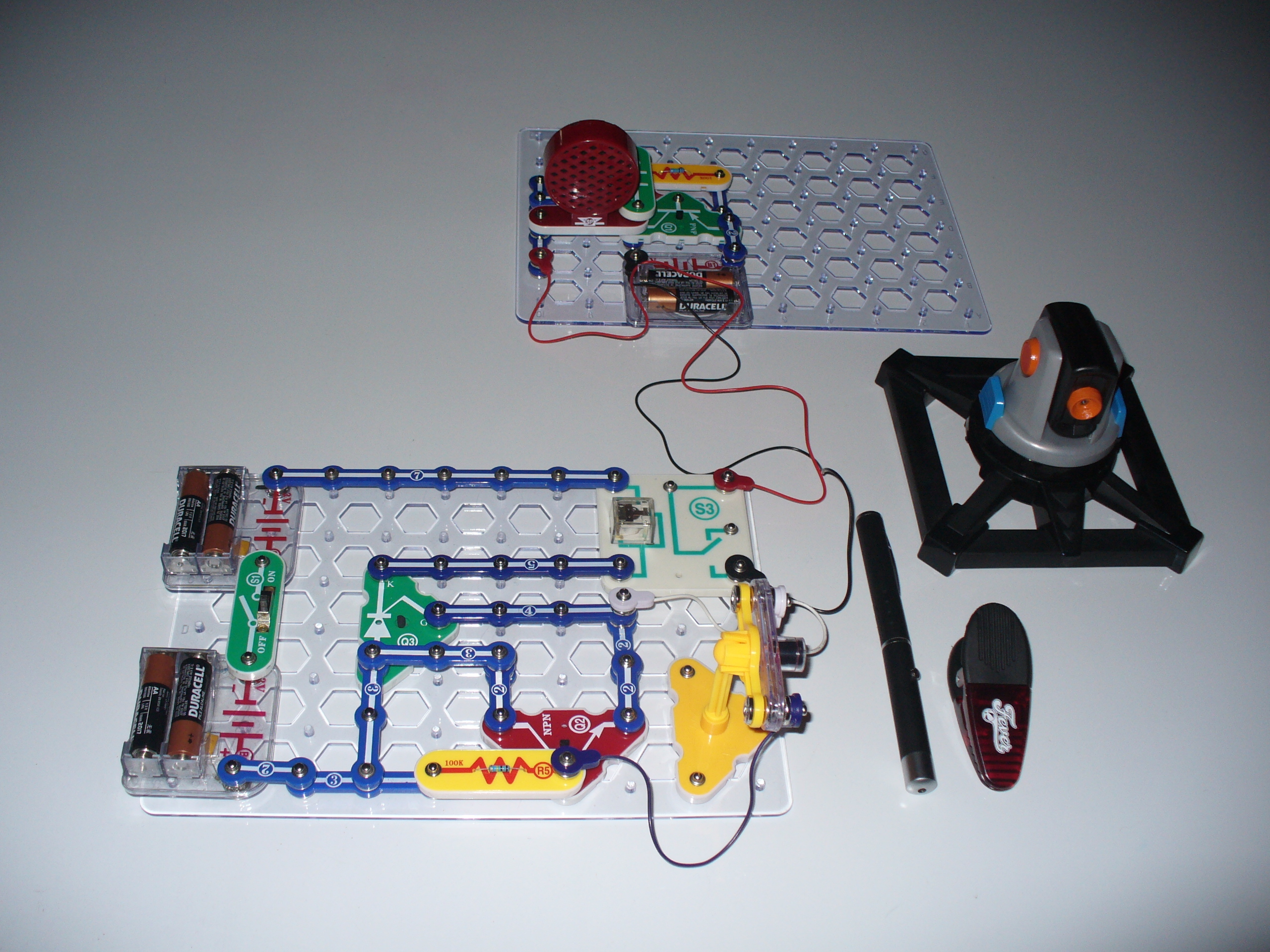
In this article you will learn how to build a laser tripwire and alarm out of Snap Circuits. You will build two circuits: the laser tripwire circuit and the alarm circuit. The alarm is a very simple two-transistor oscillator that is switched on by the relay in the laser tripwire circuit. Once you have built the two circuits, you will then learn how to set up the laser pointer where somone is likely to break the laser beam and trip the alarm. The Spynet Laser Tripwire was the inspiration for this build. I wanted to see if I could build my own laser tripwire. I also improved it by adding the relay to switch on an external circuit. I used the two-transistor oscillator as an example, but one could use the relay to switch on any number of external circuits such as floodlights, home alarm systems, etc.

Actually, the laser tripwire was an interesting problem to try to solve. In a standard transistor-SCR (thyristor) circuit, you often see an LED where I put the relay.

The SCR is advertised as a latch-on device–once switched on, it is supposed to stay on, but it don’t work as advertised:

If you replace the relay with an LED and break the laser beam (or other light source), that is, stop the light source from shining on the LDR (light dependent resistor) the LED switches on as advertised. When you restore the light shining on the LDR, however, the LED switches back off again.

So, I decided to insert the relay to switch on another circuit that would stay on even when power was cut to the relay. Oddly enough, the relay somehow keeps the SCR switched on but I’m not sure why.

In a single stroke (and by sheer accident!) I solved the problem and can now switch on any external circuit via the relay without having to add any additional components to make the externlal circuit remain on. And it will remain on until I switch the power off to the laser tripwire circuit.

Wierd. But it may be useful to others working on any number of “electric eye” applications

All Snap Circuits parts used here come from two sets: Snap Circuits Extreme 750, and Snap Circuits Green. Both sets are available at your local RadioShack store. Individual parts can be ordered from http://cs-sales.net/sncirepa.html if needed

Project Steps

Overview

Snap Circuits is an educational toy that teaches electronics with solderless snap-together electronic components. Each component has the schematic symbol and a label printed on its plastic case that is color coded for easy identification. They snap together with ordinary clothing snaps.

The components also snap onto a 10 X 7 plastic base grid analogous to a solderless breadboard.

All the kits include manuals printed in color with easy-to-follow diagrams to assemble the projects. The illustrations for each project look almost exactly like what the components will look like on the base grid when finished.

Because the electronic symbol is printed on each electronic component, once the project is completed, it will look almost exactly like an electronic schematic.

Assembling the alarm circuit.

The alarm circuit is a very simple two-transistor oscillator circuit.

When the laser tripwire relay closes the alarm circuit (switches the alarm circuit on), here’s what happens:

Step 1. The 0.02uF capacitor C1 begins to charge up. Once the capacitor has enough charge, it will switch transistor Q2 on.

Step 2. When Q2 switches on, this causes transistor Q1 to switch on.

Step 3. When Q1 switches on, it supplies power to the speaker which makes a sound.

Step 4. Capacitor C1 begins to discharge to ground.

Step 5. Once the charge in the capacitior is low enough, this switches transistor Q2 off.

Step 6. When Q2 switches off, this will switch off transistor Q1. When Q1 switches off this cuts the power to the speaker and the speaker stops making a sound

Step 7. Go back to step 1. This process repeats over and over again, ad infinitum, and you hear a high pitched tone until you cut the power to the circuit.

Laser Tripwire part 1.

The photoresistor acts as a dark detector. As long as the laser beam shines on the photoresistor, this reduces its resistance. Since resistance in this part of the circuit is reduced, current can flow to the base of the transistor Q2 switching it on.

While Q2 is switched on, current will not flow to the SCR Q3. Once the laser beam is cut, that is, blocked from shining on the photoresistor, the photo resistor will increase its resistance and current will be cut from the base of the transistor Q2. When Q2 is switched off, current can then flow to the SCR Q3 switching it on.

When Q3 is switched on, this will power the electromagnet of the relay.

Laser Tripwire part 2.

You’ve probably seen a relay race where one runner hands off a baton to another runner. Similarly, an electronic relay hands off control from one circuit to another. A relay is a very simple device consisting of an electromagnet, an armature (a switch that closes when attracted by the electromagnet), and a spring that is connected to the armature.

Laser Tripwire part 3.

When the SCR Q3 is switched on, current flows to the relay charging up the electromagnet. The electromagnet creates a magnetic field that attracts the armature to close the alarm circuit (switches the alarm circuit on), and you hear the high pitched tone created by the alarm circuit.

Laser Tripwire part 4.

What’s interesting about the SCR is that once it is switched on, it remains on providing current to the relay and the alarm sound will remain on until you turn the slide switch S1 off.

Laser Tripwire part 5.

After a person or object passes through the laser beam, the beam will shine on the photoresistor again reducing the resistance. Normally this would restore the current to the base of transistor Q2.

This would then switch Q2 on again, cutting the power to the SCR Q3 switching it off and thus cutting the current to the relay’s electromagnet switching the alarm circuit off.

But, in the case of this circuit, the relay seems to be drawing enough power from the batteries to keep the SCR switched on and preventing the transistor from switching on again and cutting the power to the SCR.

In the case of the green laser pointer, you have to hold the on/off button down to fire the laser and when you release the button, the laser switches off. So, you have to have a method of holding the laser pointer switch in the “on” position.

One easy method is to take a twist tie from a loaf of bread and wrap it around the laser pointer and the on/off button and then twist the tie tightly so that it holds the switch in the “on” position. I, on the other hand, use a different method to keep my green laser pointer switched on.

I, serendipitously, found that the Indiana Fever magnetic chip clip opens wide enough to insert my green laser pointer in its jaws. The chip clip also has a set of sawtooth teeth that catch on the barrel of the laser pointer holding it in position and preventing the clip from slipping off the barrel.

Also the chip clip clamps on the on/off switch and is strong enough to hold it in the “on” position. The clip can also be used as a stand to raise the laser pointer off the ground. You’ll have to stack something underneath the laser pointer to aim it at the photoresistor–in my case I used a couple of packs of peanutbutter crackers.

No worries if you don’t live in Indianapolis nor attend professional or minor league sports events. You can probably find one of these chip clips being given away free with the appropriate corporate logo stamped on them at conventions, Earth Day celebrations, county/state fairs and so on.

In this picture I used the Spynet Laser Tripwire laser. It is much easier to aim at the photoresistor since it has two axes of rotation–vertical and horizontal.

To set the laser tripwire ensure that the laser beam is set across a space where someone is likely to break the beam such as across a doorway or across a hall.

Recall too that that the laser dot from the pointer will project a fairly long distance so you could bounce it off a set of mirrors around the entire perimeter of your home so that anyone walking on to your property will break the beam.

For example, if your neighbor down the street lets his or her dog do its business on your lawn without cleaning up after it, you can catch him or her in the act.

Once you have the laser dot positioned on the photoresistor, turn the circuit on by moving the slide switch S1 to the “on” position. Pass your hand through the laser beam to test it. You will hear the relay click and the alarm sound. Switch the circuit off and back on again to reset it.

You can watch a video of the Laser Tripwire being demonstrated here.