This guide will tell you how to assemble your very own LED Name Tag Kit from the Maker Shed! This is a great beginner-to-intermediate soldering project that is more challenging than the Learn to Solder Badge Kit but easier than an LOL shield.

What will the next generation of Make: look like? We’re inviting you to shape the future by investing in Make:. By becoming an investor, you help decide what’s next. The future of Make: is in your hands. Learn More.

Project Steps

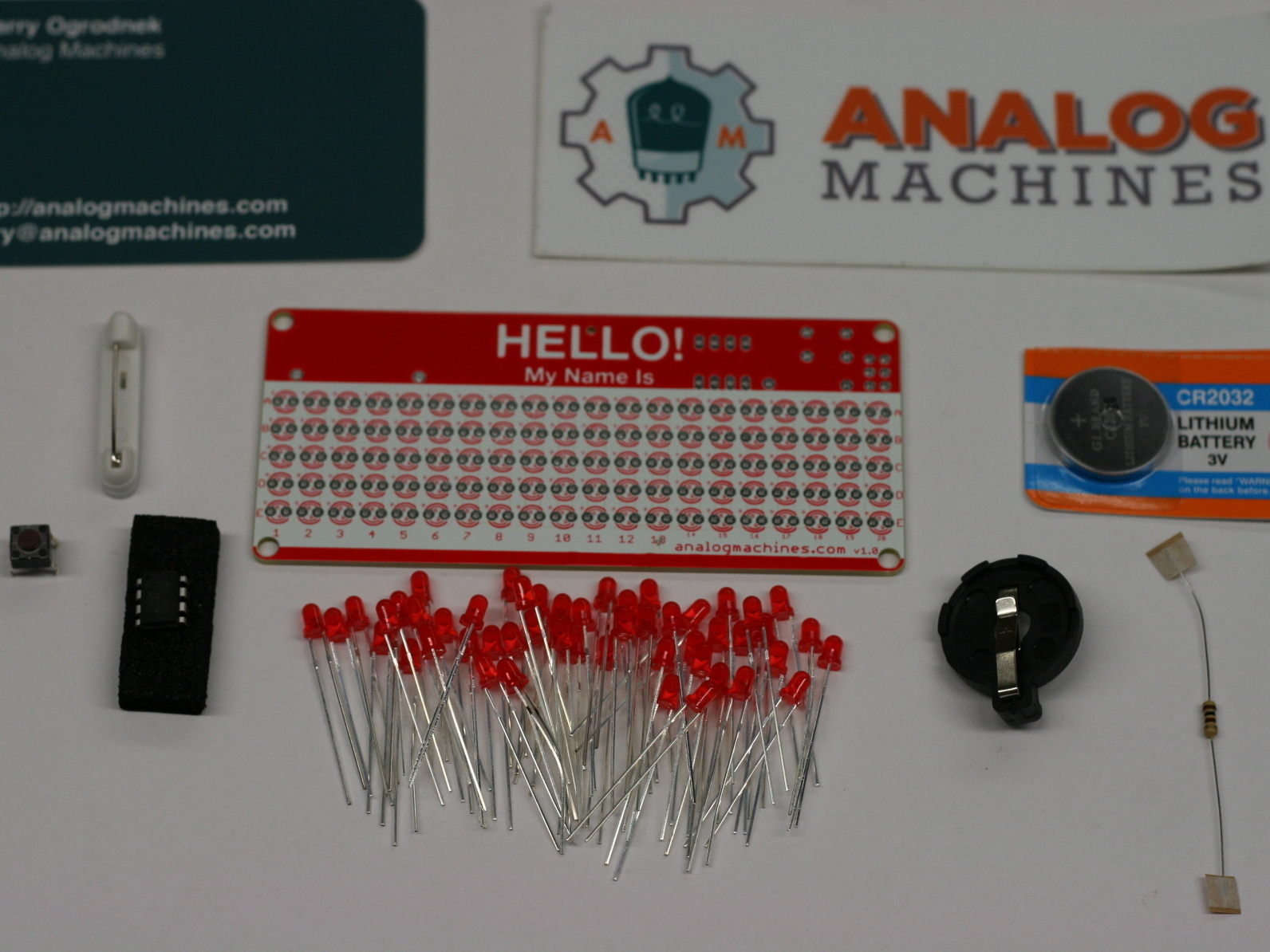
First, purchase an LED Name Tag Kit from the Maker Shed and make sure you have all the parts. The kit includes: 50 red LEDs, a microcontroller, a pushbutton, an adhesive pin, a battery, a battery holder, and a resistor. I also received a bumper sticker and I put it on my forehead. I don’t recommend doing that.

Visit the Analog Machines name tag layout page and type your name into the layout tool. Keep in mind that the kit can only fit 5 characters. If your name is longer than 5 characters you might have to shorten it, use your initials, use someone else’s name, or use a nickname.

Grab an LED. You’ll notice that one leg is longer than the other. This isn’t a mistake! The long leg of the LED goes in the hole with the + sign. The shorter lead goes in the other.

After you get the LED in, bend the legs out slightly so the LED doesn’t fall out when you turn the board upside down for soldering. Repeat this with all the LEDs in the character you are making.

At this point you should have all your LEDs for the character in place. If you are making an M or a W you’ll be adding an extra LED in the middle of the character. This LED must be reversed from the rest of the LEDs because you’re going between the columns. The positive is on the RIGHT-hand hole now.

When you have all your LEDs in place go ahead and turn the board over for soldering.

Now, use your soldering iron and solder the leads. After soldering is complete clip the excess off using your side snips. Watch your eyes when you do this!

Now, do the same for your next character. Wash, rinse, and repeat!

After all your LEDs are in place and soldered, it’s time to move on to the microcontroller!

The IC goes into the holes marked IC1. This chip will control the various display options on your nametag.

The chip legs probably won’t fit into the holes because they are too far apart. To fix this, gently “roll” the legs on a flat surface to bend them in. Repeat this on both sides a little bit each time until the legs fit into the holes.

Pay attention to the little notch or dot on the chip. This marks the way the chip should be oriented on the PCB. The direction of the indentation or dot should match the printing on the PCB.

After the chip is inserted correctly, bend a few of the legs that stick out from the back so that the chip does not fall out when you turn the board over for soldering.

Solder the legs of the chip into place and use your side snips to trim off the excess.
Next, we’re going to add the pushbutton. The button looks like, well, a button. It’s going to go on the front side of the PCB. It fits in two ways and either way is fine. Press it into place and it will snap into position.

Now, turn the PCB over and solder the button into place then snip off the excess with your side snips.

Next, we’re going to attach the battery holder. It’s black with a silver piece and it looks like it could hold a battery!

Situate the battery holder to that its footprint matches the outline on the PCB. These leads are a little hard to bend so you might want to put a piece of masking tape on it so it doesn’t fall out when you turn the board over for soldering.

Once it’s soldered, clip the excess leads off with your side snips.

Up next is the resistor. It’s brown with stripes and it looks just like a resistor should. Usually these come with paper bits stuck to the ends. I just cut them off to avoid the sticky residue that can result from just pulling them off.

The resistor goes on the front or back of the PCB. I put mine on the front just for fun. Just feed the legs through the holes marked “R1,” bend them slightly, and solder them into place.

Cut the excess with the side snips once the resistor is soldered.

Finally, let’s stick on the pin. It has a paper backing that peels off like a sticker. Stick it onto the top center of the PCB between the battery and the chip.

Now, let’s put in the battery. It goes writing side (+) up.

Now you’re ready to light it up! Hit the button to toggle through the 4 display modes.

Now bask in glowing goodness of the LED nametag kit you just made!

When not using your name tag, we recommend that you remove the battery so that the battery lasts longer. Even with the name tag in the “off” mode the chip still draws a bit of current. Removing the battery will ensure that your name tag will light up when needed!

Conclusion

This is a great kit that really makes your name stand out in conferences!