[youtube:http://youtu.be/Xz0QuQ0o8v8]
For more on microcontrollers and wearables, check out Make: Volume 43.  Don't have this issue? Get it in the Maker Shed.
For more on microcontrollers and wearables, check out Make: Volume 43.
Don’t have this issue? Get it in the Maker Shed.

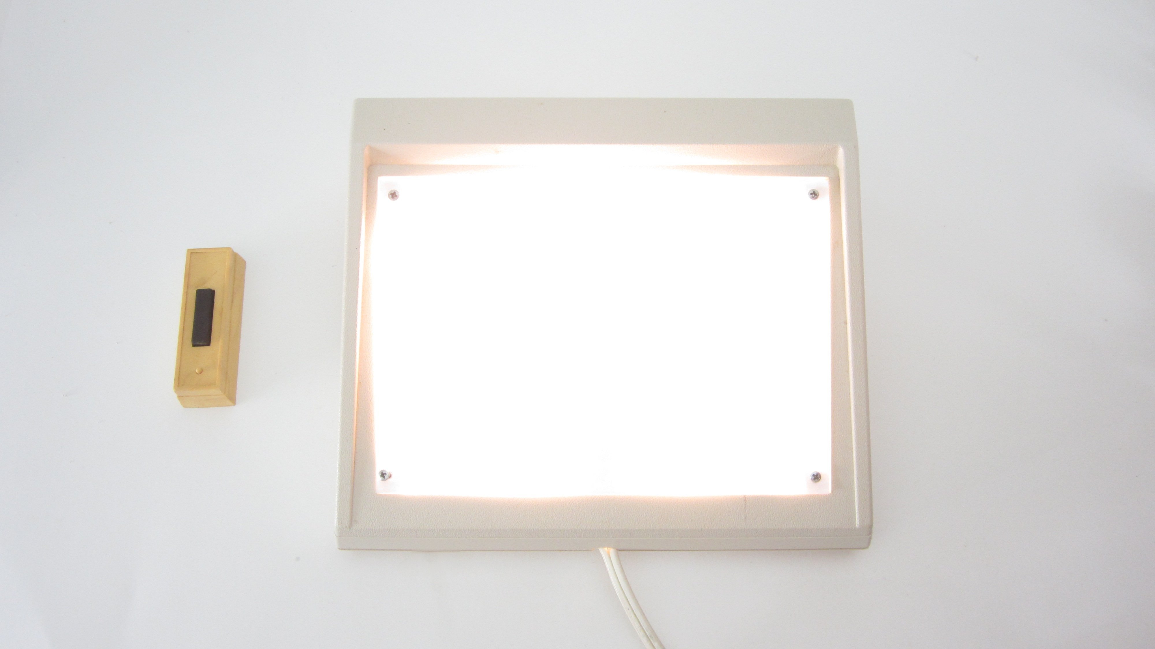
When I am using power tools in my workshop, I can’t hear the doorbell ring. I needed some other kind of system that can let me know when someone is at the front door, so I modified a wireless doorbell system to turn on a light in addition to playing a tone. Using wireless doorbells, you can set up multiple receivers without having to run wires all over your house. Here is how to make it.

View this project on Instructables: instructables.com/id/Doorbell-that-Turns-on-a-Light/

edited_IMG_2162

What will the next generation of Make: look like? We’re inviting you to shape the future by investing in Make:. By becoming an investor, you help decide what’s next. The future of Make: is in your hands. Learn More.

Project Steps

Background: How a Typical Wireless Doorbell's Power Supply and Sound Player Work

There are a lot of parts that make up a wireless doorbell. But for this project, you only need to be concerned with the power supply and the speaker.

An AC powered wireless doorbell is going to have an AC-to-DC converter to turn the 120 volts AC into a small DC signal (usually about 12 volts). To bring the voltage down, it may use a transformer or just a power resistor. Then to convert the AC sine wave signal to a series of DC pulses, it will typically use four diodes arranged as a square bridge rectifier. Lastly, a capacitor smoothes out the DC pulses into more constant DC signal.

We need to identify the positive and negative DC lines at the output of the AC to DC converter. The easiest way to do this is to observe the orientation of the capacitor: One side of the capacitor will be marked with a large negative sign. This is connected to the negative output of the power supply. The other side is connected to the positive output of the power supply.

Next you need to check how the speaker is connected to the rest of the circuit. In most cases, the positive terminal of the speaker will be connected to the positive supply voltage from the power supply. The negative terminal of the speaker will be connected to the collector of an NPN transistor. The emitter of the transistor will be connected to the negative terminal of the power supply. The base of the transistor will be connected to processor chip. There may be a resistor between them. To play the tone, the chip sends a series of pulses to the transistor, which rapidly connects and disconnects the negative terminal of the speaker to the negative terminal of the power supply. This causes the speaker to play a tone.

In this project we will be connecting to the positive and negative terminals of the power supply and to the output transistor at the negative terminal of the speaker.

Cut the Speaker Wires and Attach Extension Wires

The first thing that you need to do is cut the speaker wires near the center. Then strip the insulation off of the ends. Solder another six-inch piece of wire to each one. (It helps if you keep them color coded.) Insulate each connection with either heat shrink tubing or electrical tape.

Solder an Extension Wire to the Negative Terminal of the Power Supply

Next, we need to connect a wire to the negative terminal of the doorbell’s power supply. As mentioned earlier, the easiest way to identify the negative output of the power supply is to check the terminals of the capacitor. The side of the capacitor that is labeled with a large negative sign “-” is connected to the negative terminal of the power supply. Find any terminals that are connected to this and solder on a piece of wire that is about eight inches long.

Drill Holes to Route the Wires Outside of the Doorbell Housing

Find a drill bit that is the same size as the extension wires and drill five holes in the housing of the doorbell. Then feed the wires through them and close up the housing. Be sure to keep track of which wires are connected to what. It may help to label the wires with a small piece of tape.

Attach Two Switches to the Output Transistor

Now we need to connect to the output transistor. This is the wire on the board that used to be connected to the negative terminal of the speaker. First, take this wire and connect two more extension wires to the end of it. Then solder a sliding switch onto the end of each one. These switches will let us turn the tone and the light on and off.

One switch will be used to control the audible tone of the doorbell. To set this up, take the wire that is connected to the negative terminal of the speaker and solder it to one of the switches. When the switch is turned on, it will connect the speaker and the tone will play.

The other switch will be used to control the light. On this switch, solder another extension wire. This wire will be connected to an external circuit that will turn the light on and off.

The Control Circuit

The control circuit is a basic 555 timer circuit. This configuration is called “Monostable” mode. Vcc and GND for this circuit are connected directly to positive and negative terminals of the doorbell’s power supply. Pin 2 (the trigger pin) is connected to the free wire on the second switch. When the doorbell is activated, pin 2 is connected to ground through the output transistor. This causes the output at pin 3 will turn on for a length of time that is determined by the values of the capacitor and the resistor.

You can determine this time using the formula:

Time(in seconds) = 1.1 x R(in ohms) x C(in Farads).

Prototype and Troubleshoot the Circuit on a Breadboard

As with any electronics project, you should first test the circuit out on a breadboard. I attached an LED to the output for testing. In the final version, the output would be connected to the solid state relay.

Here are some common problems that you may encounter and how to deal with them:

If the output of the power supply is not stable enough, it can cause the timer circuit to malfunction. To fix this, add an additional capacitor between the doorbells. I used a 330 microfarad capacitor.

If pin 2 is connected directly to the output of the doorbell and nothing else, it can experience some interference from static electricity. This can cause false triggering. To solve this, add a 1kohm resistor between pin 2 and pin 4 (the positive supply voltage). This acts as a pull-up resistor and keeps the pin HIGH until it is pulled LOW by the signal from the doorbell.

Solder the Circuit Onto a Printed Circuit Board

Once you are happy with how your circuit is performing, solder all the components onto a printed circuit board.

Connect the Output of the Circuit to the Solid State Relay

Now we need to connect the control circuit to the solid state relay. Connect one wire from pin 1 (ground) on the control circuit to the negative input terminal on the solid state relay. Then connect pin 3 (the output) on the control circuit to the positive terminal on the solid state relay. I recommend insulating the connections with heat shrink tubing.

Cut the Extension Cord

The extension cord needs to be cut into several sections in order to provide power to the various parts of the system. Start by cutting the cord 6″ from the female end. Then cut another section that is about 1′ long. Separate the two wires of this 1′ section. Cut one of these separated pieces in half. Lastly, strip the insulation off the ends of each piece.

Connect the Wires With Twist-on Connector Caps

There are two sets of wires that need to be connected. First take one wire from the male end of the power cord, one wire from the female end of the power cord, and one of the short separated wires. Connect these three with a twist-on connector cap. Then take the other wire from the male end of the power cord, the other wire from the female end of the power cord and the long separated wire. Connect these with a twist-on connector cap.

Connect the Power Cords to the Solid State Relay

Now take the two short separated wires from the power cord and crimp on a pair of quick disconnect connectors. Fit these onto the load terminals of the solid state relay.

Connect the Light

I chose to use a small CFL fluorescent light as the light for this project. To connect the light, I mounted it inside a small light socket, then attached the two remaining wires from the power cord assembly to the screws on the light socket.

Cut Holes in the Housing for the Power Cord and the Switches

At this point, all the electrical components are connected. Now we need to prepare the housing. Cut one slot for the power cord and two slots for the switches. You can do this with either a knife or a rotary cutting tool.

Mount All the Parts Inside the Housing

All that is left is to mount all the parts to the inside of the housing. Start by mounting the light socket to the center of the housing. I just screwed it to an available mounting hole. Next, plug the doorbell receiver into the power cord. Secure the doorbell, the solid state relay, and the circuit board to the inside wall of the housing with hot glue. Lastly, glue the two switches into the cut slots inside of the housing. You may wish to label the switches to help keep track of them.

Use Your Light Doorbell

Plug the power cord into a wall outlet and you are ready to try out your light doorbell. The two switches will let you set how the doorbell will operate. You can have it play a tone like a normal doorbell by turning the tone on and turning the light off. Or you can set the doorbell to silent mode by turning the tone off and turning the light on. Alternatively, you can turn both functions on at the same time or you can have them both off.

This kind of a doorbell can be really useful. It can help accommodate people with hearing impairments, or it can let you silence the doorbell when someone is sleeping.