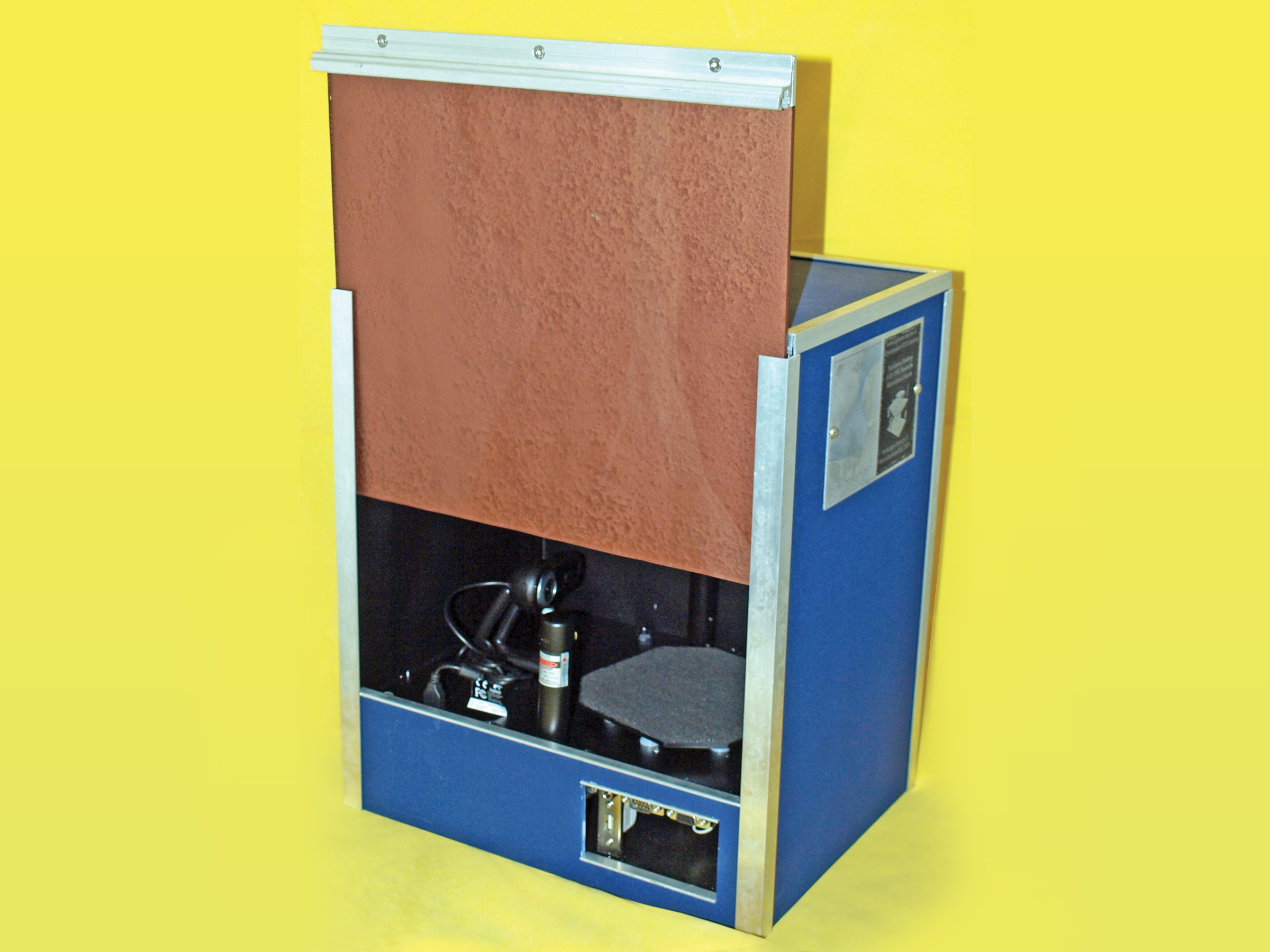
The last couple of years have seen an explosion in home fabrication, with fantastic projects like RepRap and Fab@Home really helping to bring the open source community together. Unfortunately, 3D scanning — in many ways the flipside of the home fabrication coin — seems to have fallen by the wayside.

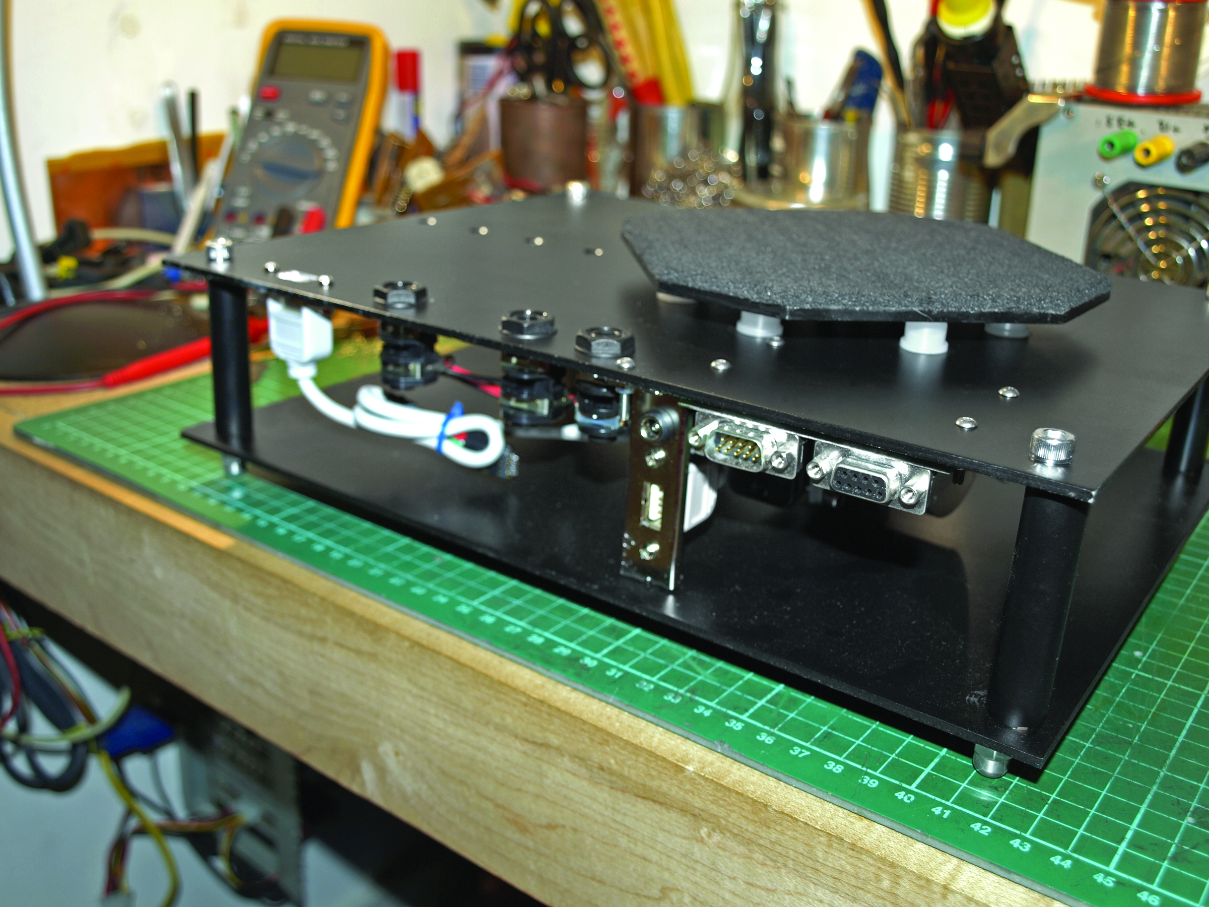
I decided to start the 3D scanning ball rolling by creating the SplineScan computer-controlled turntable. The turntable uses a gearbox for precise positioning, and has fixings for lasers, lights, and cameras. The obvious use of the turntable is for 3D scanning, although it can be adapted very easily to rotate objects for accurate photography or interactive display.

I’m currently using the turntable to archive and measure ancient artifacts as part of my Ph.D. studies (http://www.mara-3d.org), and I have to say that I’m very happy with the results so far.

The parts list might look a bit daunting, but the project is not difficult to make. The scanner itself consists of 3 main parts:

Chassis This is the backbone of the scanner. Everything fits onto the chassis, and it needs to be rigid enough to withstand the weight of all the other components, and whatever you intend to put onto the turntable.

Gearbox This part takes the turning force of the stepper motor and turns it into something more suitable for our needs. It’s a simple design with only a few components.

Electronics The brains and nerves of the scanner allow you control the turntable from your computer. The wiring is not difficult, and only limited soldering knowledge is required.

What will the next generation of Make: look like? We’re inviting you to shape the future by investing in Make:. By becoming an investor, you help decide what’s next. The future of Make: is in your hands. Learn More.

Project Steps

Make the chassis.

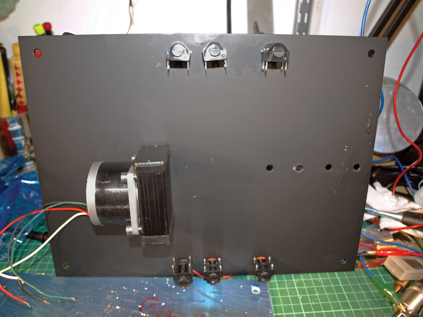
Drill 4mm holes in the corners of the top and bottom plates, to accept the 65mm bolts that hold the chassis together. The 6 larger holes along the longest sides of the top plate are for the ¼” audio jacks. The outer diameter of the jack may vary depending on the brand you use.

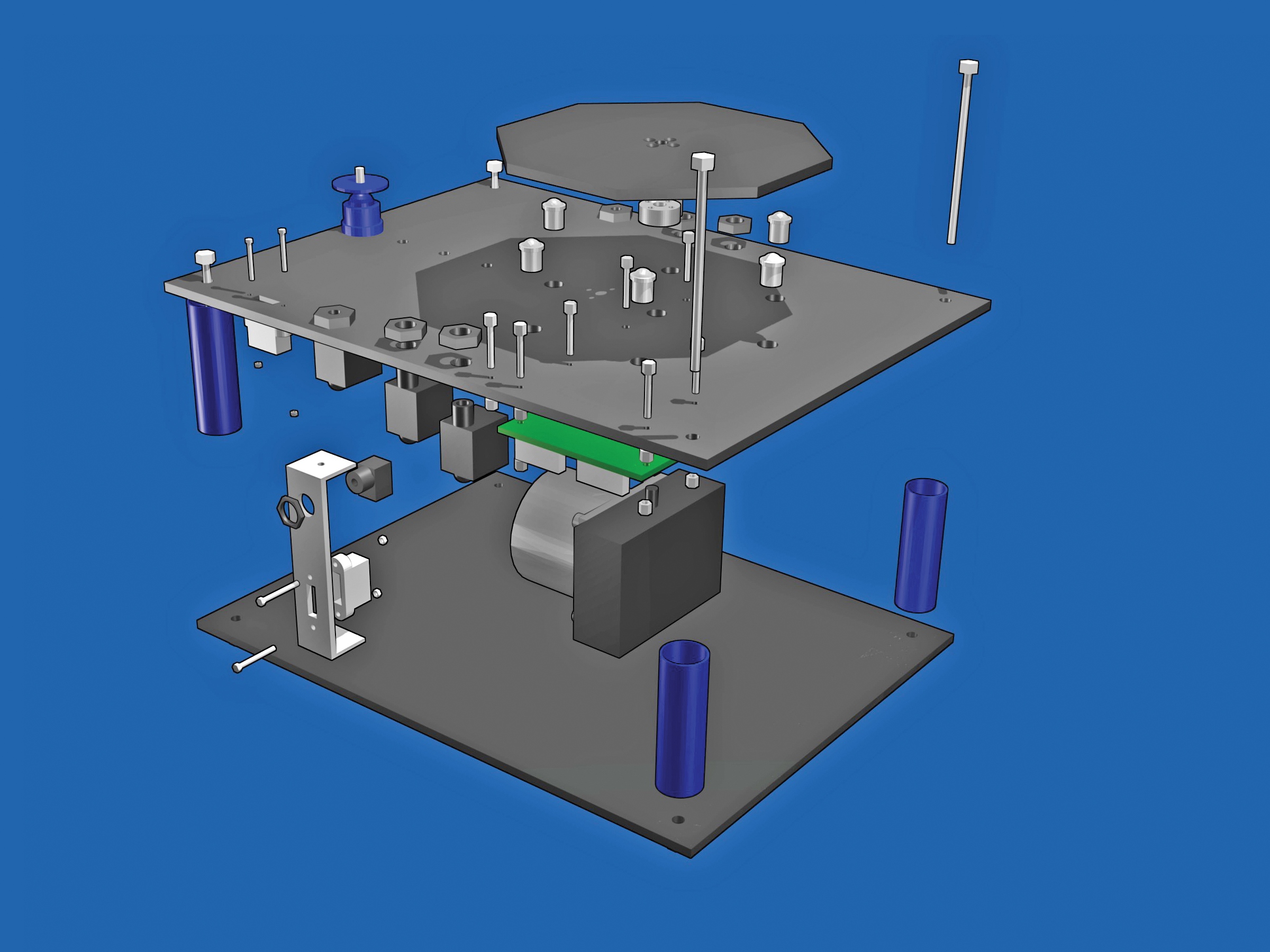
Use the exploded parts diagram and the template to decide on the hole sizes for the other parts of the chassis. Hole sizes will vary depending on product brands, and the best rule (after “measure twice, cut once”) is to start small and drill bigger if need be.

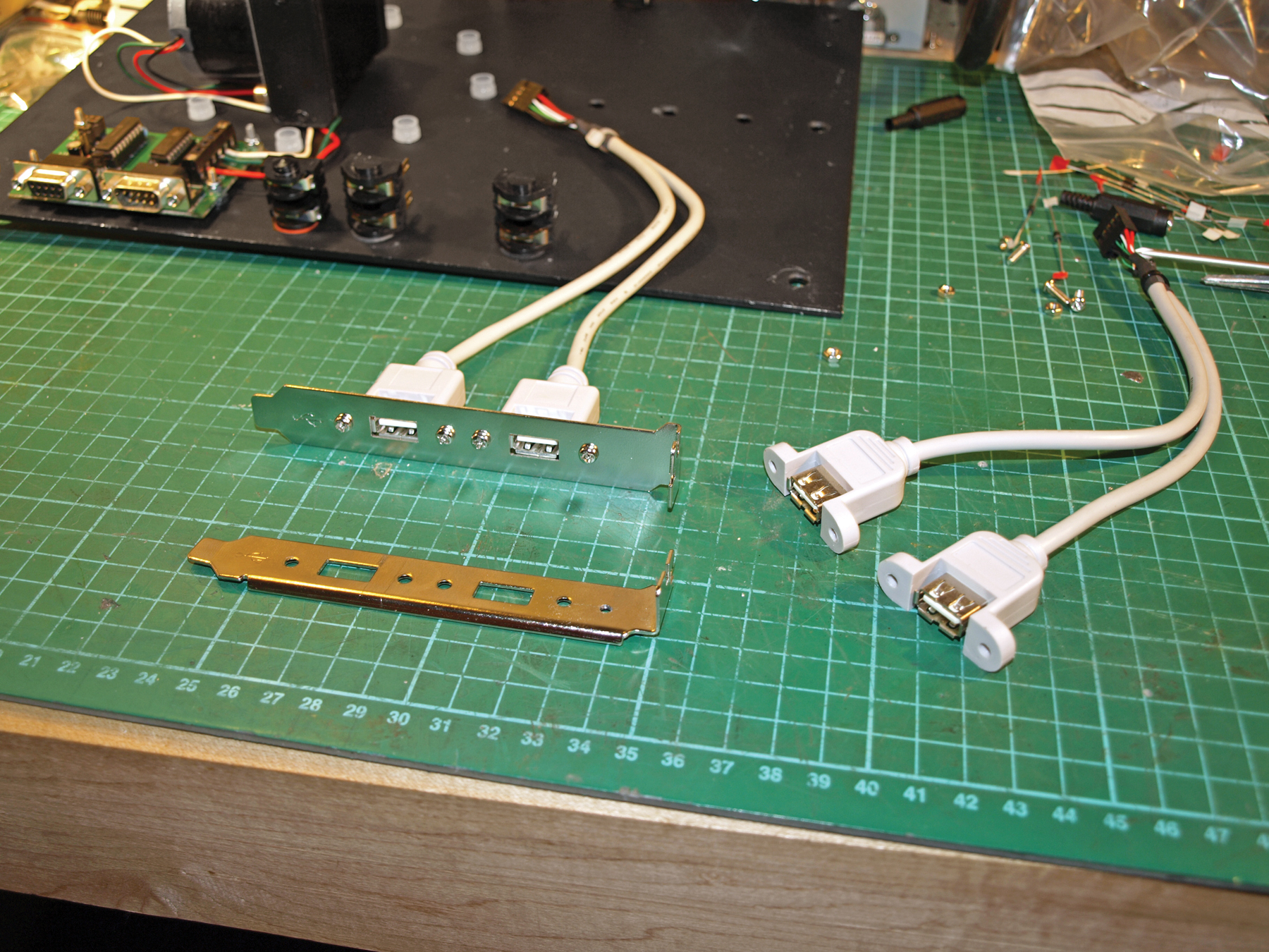
The small oblong marked on the top template is just a guideline for positioning the USB socket. The best source of USB sockets is a computer port extender that fits inside your computer and connects to the motherboard . Most computer shops have these on the shelf, but the design isn’t standard and the mounting holes can be in any position. If you want to fit your USB socket to the chassis, now’s a good time to mark and drill the holes using your socket as a template.

The 2 aluminum plates are held together by 75mm M4 bolts and spaced apart by bits of copper (or plastic) pipe. The exact diameter of the pipe is not important. Cut four 65mm lengths of pipe and put one at each corner of the top and bottom plates. Feed the bolts through the corner holes in the top and bottom plates, and secure them temporarily with a nut. Make sure everything lines up correctly, and then disassemble the parts again.

Now that all the holes are drilled, you can apply any finishing touches, like painting the copper and aluminum, and polishing any plastics.

The turntable is supported by 6 plastic ball casters, which can be pushed into place at this stage. These should be a tight fit, but a little glue won’t do any harm.

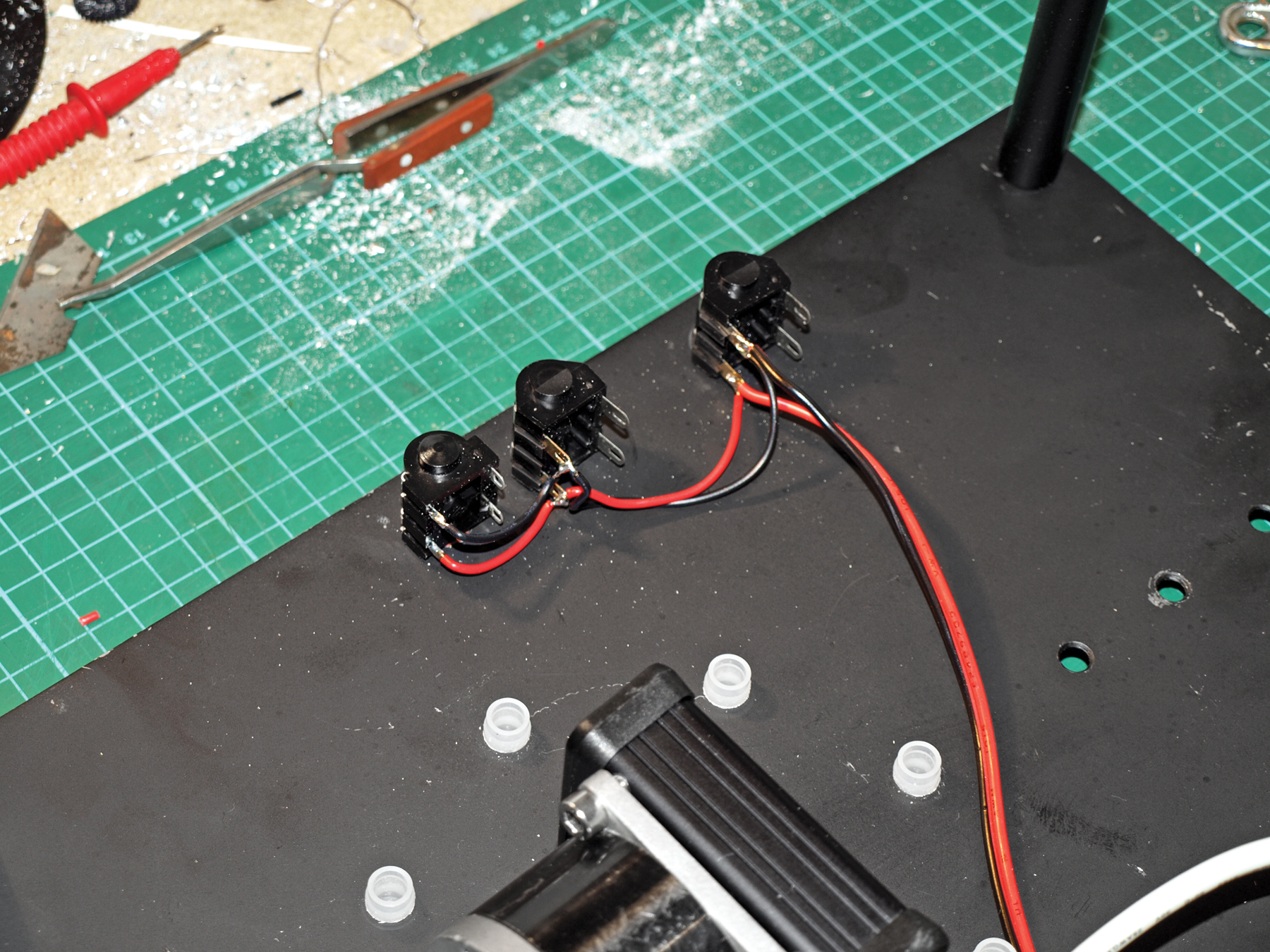
Install the six ¼” jacks, which go down both sides of the top plate; these will let you use 2 laser modules in various positions. With that done, you can turn your attention to the gearbox and motor.

Make the gearbox.

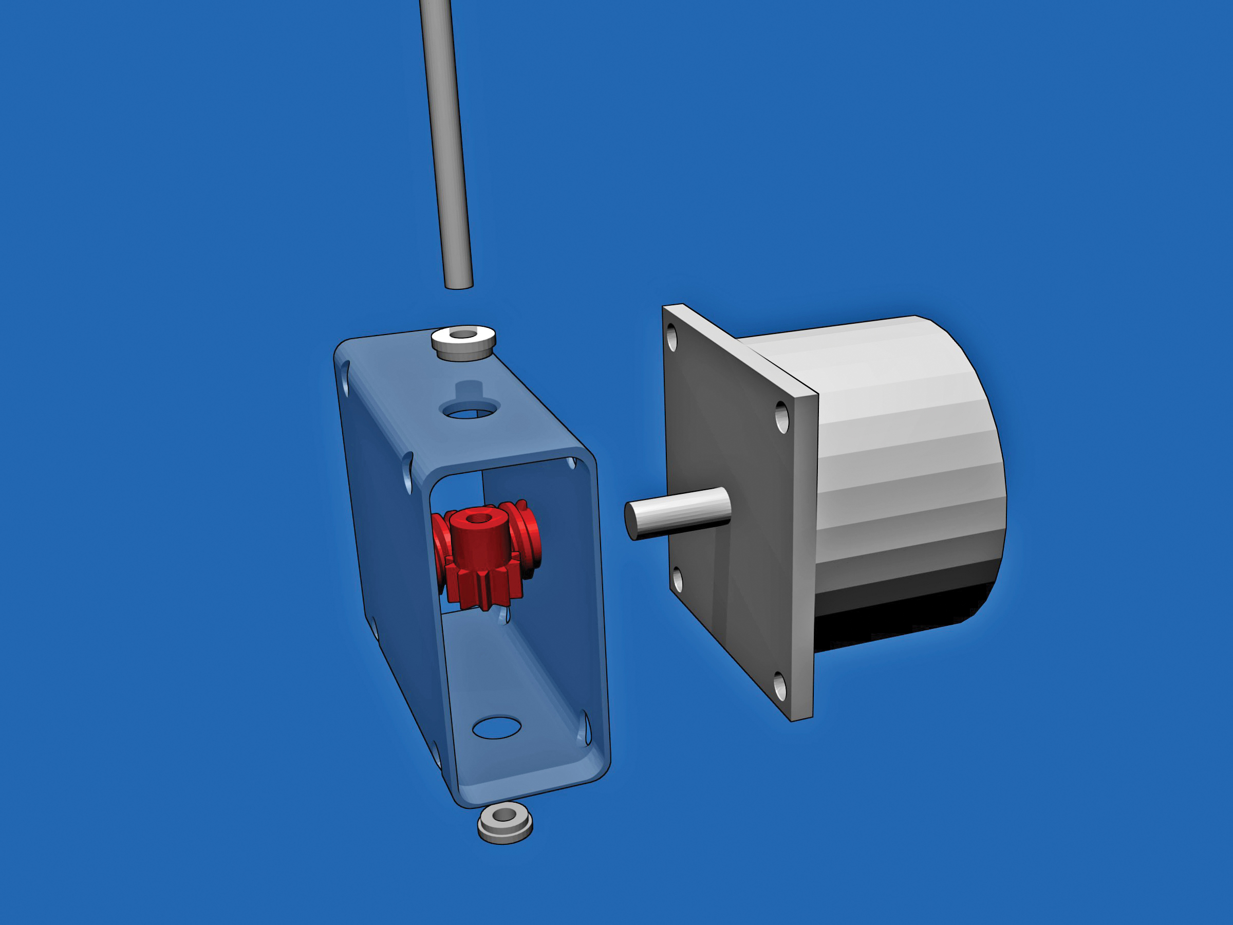
Drill a hole through the center of the largest side of the box, to allow the shaft and the plastic worm drive to pass inside. Drill holes at the corners of the box that line up with the mounting holes on the motor, using the motor as a template.

Next, enlarge the hole in the plastic worm drive to 6.5mm so it will fit onto the motor shaft, and cut the worm drive to the length of the motor shaft. It should be a tight fit, and you might want to dab a little epoxy on the end to make sure the shaft stays put.

Drill 8mm holes through the narrowest sides of the box, to house the miniature shaft bearings. This step is quite tricky; the holes need to be positioned so that plastic cog and the worm gear mesh together accurately. Measure carefully, and allow plenty of tolerance in the motor mounting holes. Remember that it’s much easier to reposition the motor than to reposition the bearings.

Push-fit the bearings into the holes (they shouldn’t need glue) and then slide the shaft through the first bearing. This will be quite a tight fit, and might need a gentle tap with a heavy object to push the shaft through.

Now fit the motor (with the worm drive on the shaft) into position and bolt it in place. You can also move the 10-toothed gear on the 4mm shaft so that it meshes with the worm gear, and fix it into position using the small setscrew on its brass hub.

Fit the end caps in place, and you’ve almost completed the gearbox. Screw the gearbox into the chassis top with M3 screws, using the top as a template for the holes in the gearbox. If you use a 3.5mm drill bit, you can tap the holes in the gearbox and screw directly into it. You may want to include some packing washers between the top of the gearbox and the top plate of the chassis, to accommodate the plastic sides of the gearbox.

Make the turntable.

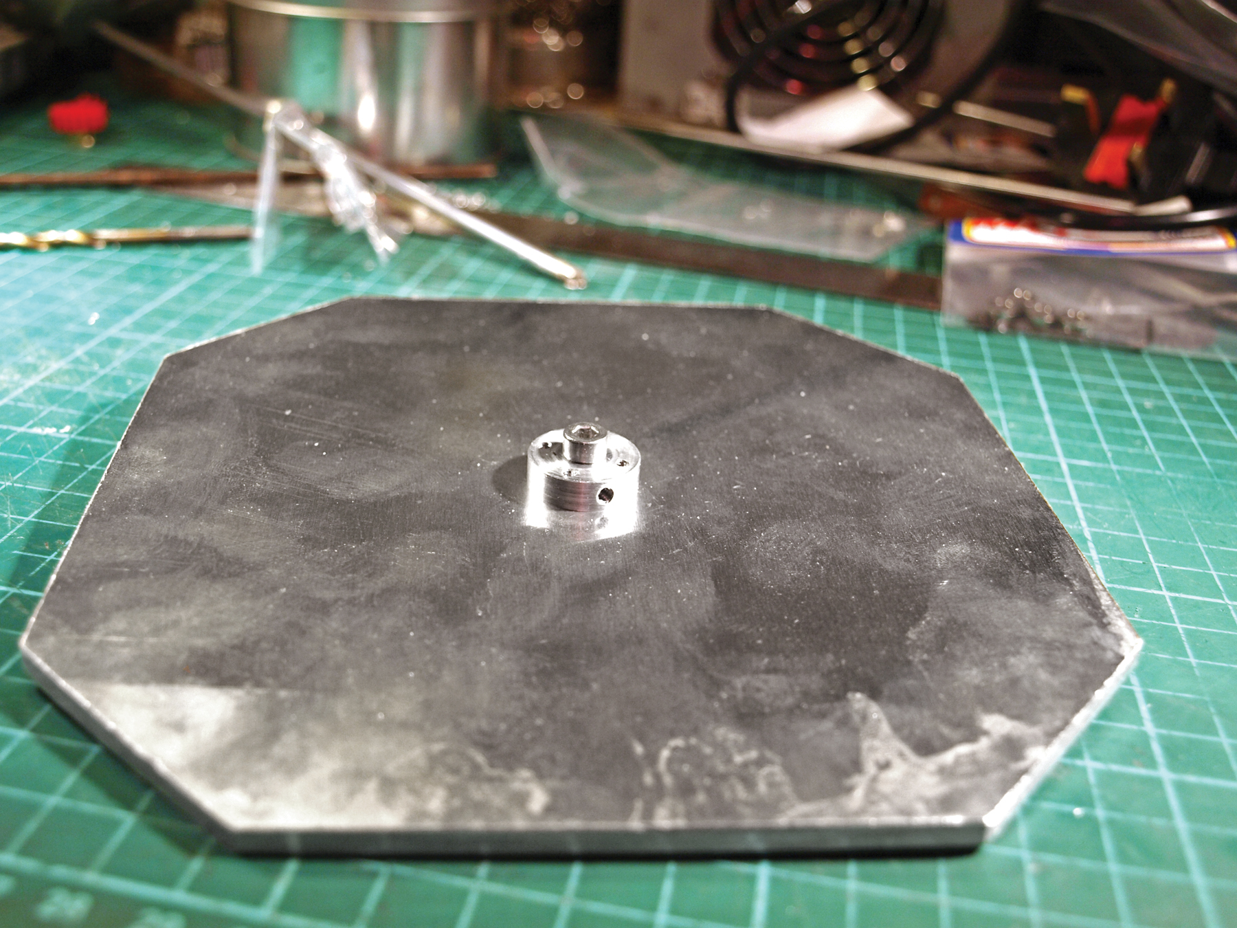
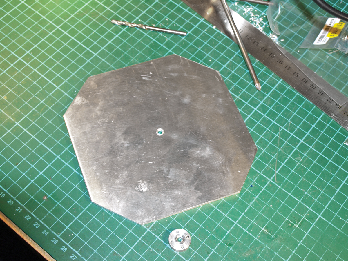
Cut the turntable from a piece of 3mm aluminum or rigid plastic using the template at splinescan.co.uk. Drill a 4mm hole in the center and fix a 4mm mounting hub in position, using a 4mm shaft as a guide. You can glue this if you wish, but I modified the hub and used 3mm countersunk bolts to hold the hub in place.

Fit the turntable in position on the chassis, and cut the shaft so it won’t protrude above the turntable. Fix the turntable onto the shaft by using a long Allen key to tighten the grub screw (setscrew) in the hub on the underside of the turntable. To finish the turntable, you can cover it in sticky-backed foam or paint it with a matte finish.

Mount the electronics.

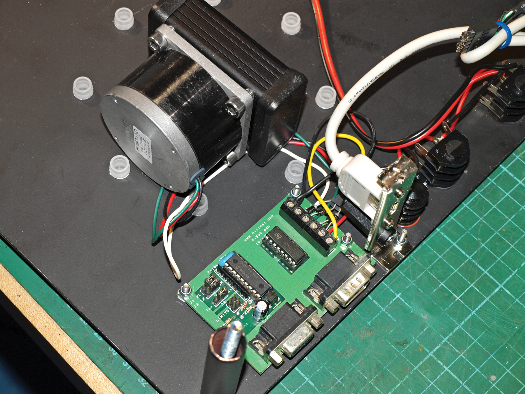
The Milford Instruments motor controller takes a serial port signal and converts it into motor movement.

The motor wires connect directly to the controller board, leaving only the power wires, which are attached to a 2.5mm DC socket on the side of the chassis.

I mounted the DC socket in an old blanking plate from the rear of a PC (the same plate I took the USB socket from). The DC socket is wired directly to the USB socket in the top of the chassis plate (red to red, black to black). Connection is made to the PC using an ordinary USB A-to-A cable. The motor controller needs 12V to operate, and

The power supply also powers the jacks. You can connect the jacks directly to power via the DC socket; this is acceptable if you don’t like soldering and you want to keep things as simple as possible.

The drawback is that the power to the jacks will be constant, meaning that any laser emitters or lights plugged into the system will always be switched on, even when the machine is idle.

A more elegant solution is to draw power from the motor, using diodes to prevent current feeding back between the coils. The advantage of this method is that when the controller board powers down the motor, any lights or laser emitters will switch off. If the motor is idle but locked, the lights will be switched on.

NOTE: You can also use an Arduino with a suitable motor shield to control the stepper motor, and future versions of the scanner may use Arduino as standard. The truth is that I already have several of the Milford Instruments controllers left over from another project, and I don’t have any spare Arduinos at the moment.

Make 2 laser emitters.

If you’re interested in 3D scanning, then you’ll need to make laser emitters to plug into the jacks. Similarly, you could make plug-in LED modules for illuminating objects on the turntable.

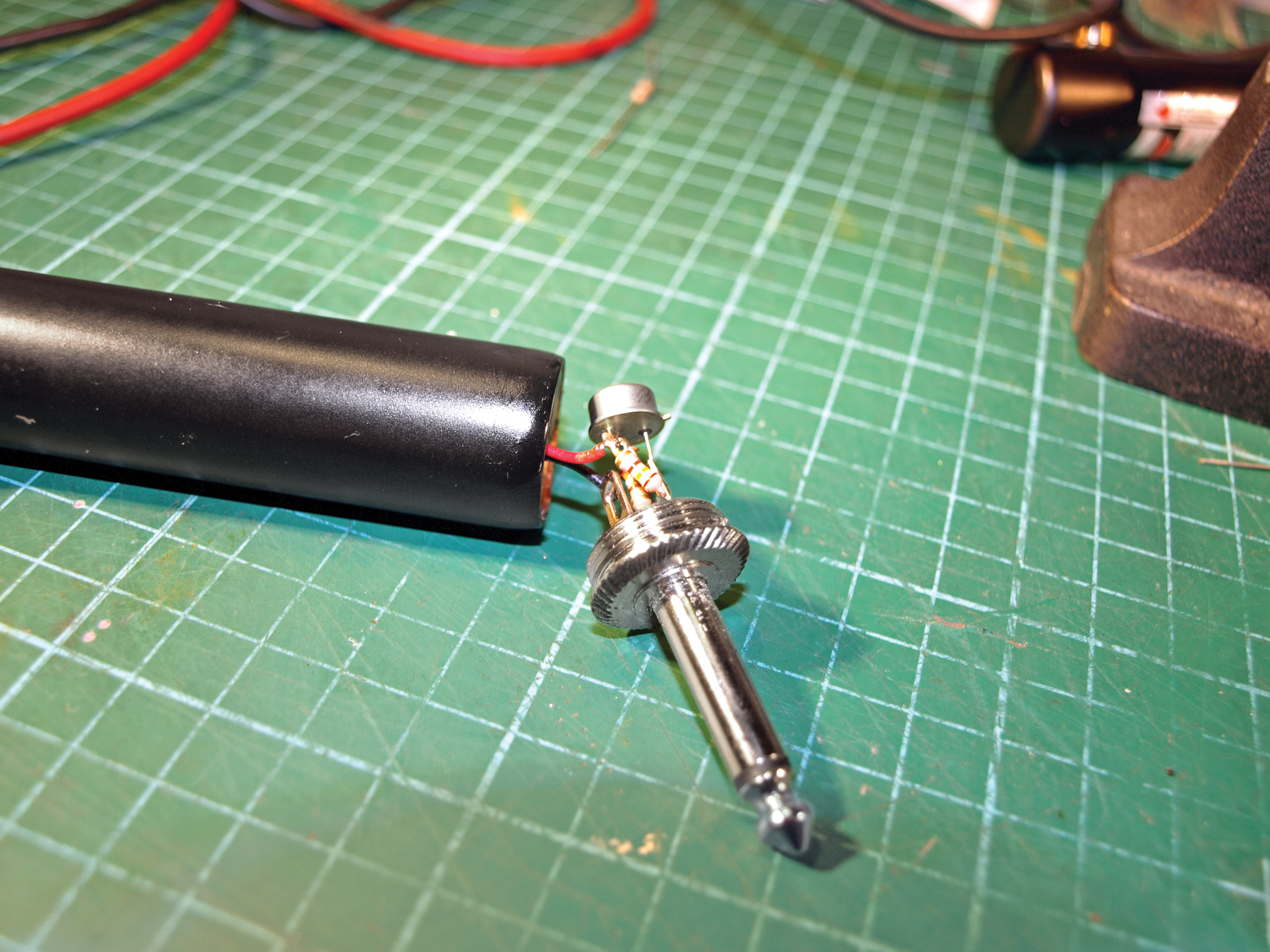
Power taken from the jacks will be around 12V, and since most laser emitters and LEDs use substantially less, you’ll need to step down the power using a monolithic voltage regulator. I recommend the LM317, which can be wired to produce a range of different voltages.

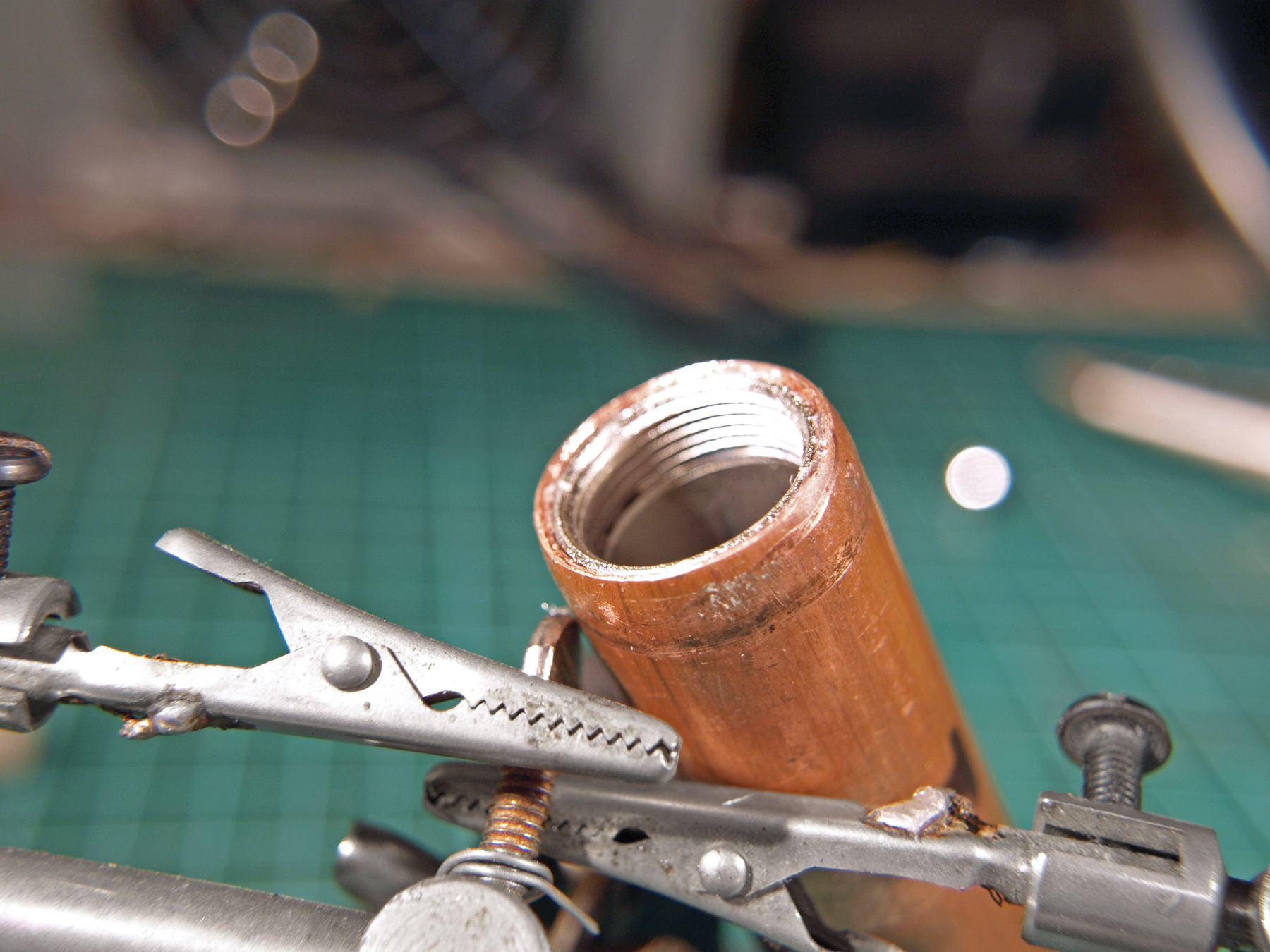
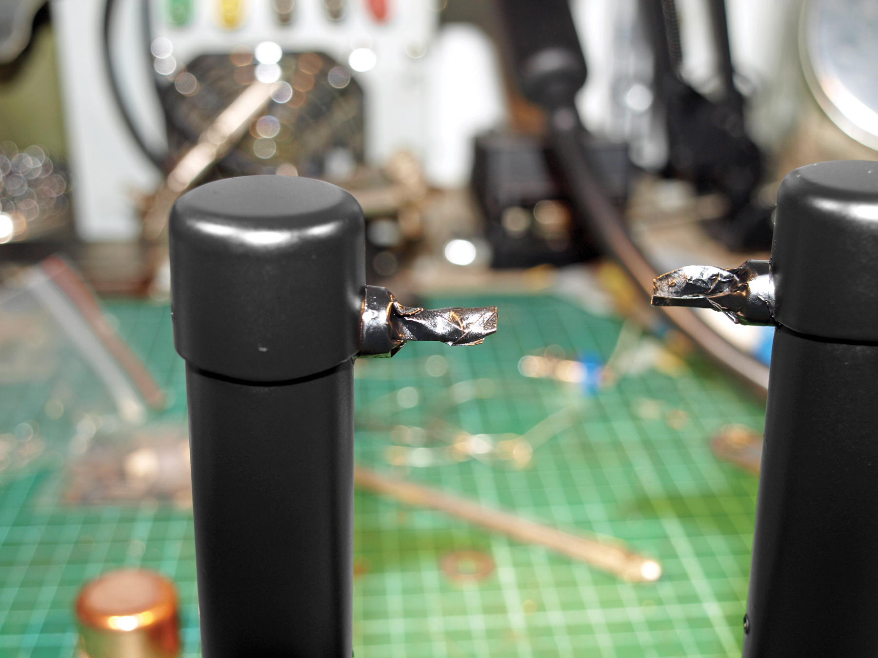
The design of the emitter casings is quite simple. I used Neutrik cast phono plugs, which fit neatly into copper pipe. I had ample space to fit the power regulator circuit and a tiny laser line generator that I got on eBay.

I used a standard plumbing end-cap to finish the top of each emitter and then painted them black, and held the copper tube onto the cast plug using a combination of hot glue and grub screws.

Install and run the control software.

Controlling the turntable is very easy using either Milford’s own software or simple serial communication. I have provided a Python library to interface with these motor controllers, motorcon.py, in the code section of my website at http://www.monkeysailor.co.uk/code.php.

My “Babylon” version of the SplineScan software (I used it to scan Babylonian stone tablets) will support this turntable directly. It’s completely open source and was released in December 2009 at splinescan.co.uk, so if you’re interested in 3D scanning then you’re in luck. SplineScan Babylon uses Python and Pygame, and has been designed to work on Linux, although it should work quite happily on Windows machines, too.

So, there you have it: an earnest attempt at a computer-controlled turntable suitable for open source 3D scanning, photography, or display. I mounted mine in an outer casing, so I can scan objects without bouncing laser light all over the room. In the future, I might even modify the design to include a moving extrusion head, and develop a polar 3D printer.

Conclusion

This project first appeared in MAKE Volume 21, page 54

Related Posts on Make: Online:

Handheld 3D Scanner

http://blog.makezine.com/archive/2008/02...

3D Scanning with a Web Cam and Projector

http://blog.makezine.com/archive/2009/02...