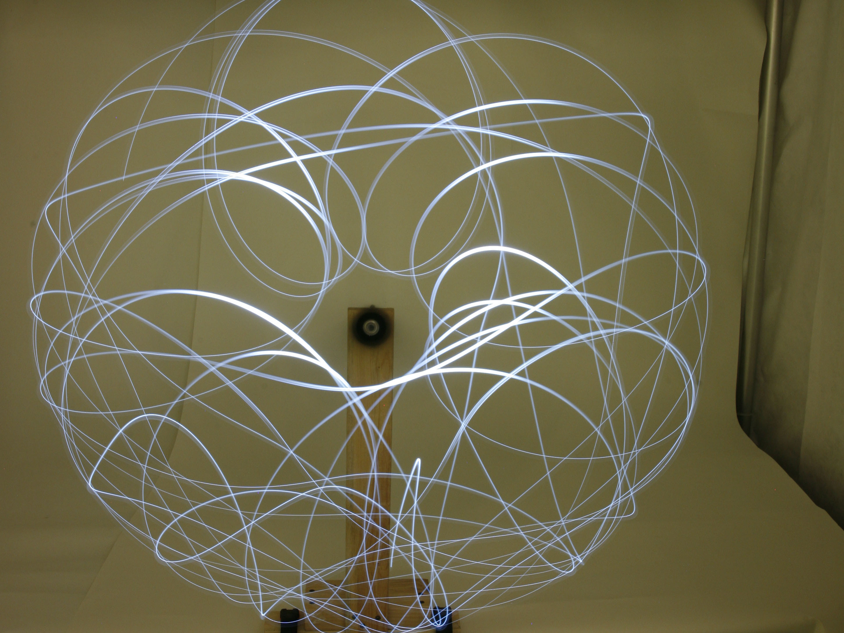
Devices that demonstrate true chaotic behavior (in a strict mathematical sense) are rare. Even rarer are chaotic devices that are easy enough for the typical maker to build at home and are interesting and beautiful. But one device nicely fits the bill: the double pendulum.

A double pendulum consists of a bar swinging from a pivot, with a second pendulum attached to the first bar’s end. While the double pendulum is a simple physical system, you’d be hard pressed to find another device this simple that exhibits so wide a range of behavior. Give it a little push and the motion is fairly predictable. But give it a bigger push — bingo, welcome to chaos!

The double pendulum described here was designed with several options for demonstrating a variety of chaotic motions. With the right mounting, it’s an interesting if not downright charming display that fits well into a number of settings, including classrooms, laboratories, and homes.

YouTube player

Project Steps

Cut the pendulum parts.

The pendulum itself may be fabricated from any number of common materials including plastic, aluminum, and wood; I used polycarbonate plastic.

The exact size of the pendulum may vary according to the wishes of the maker. I ordered my materials from McMaster-Carr because they were easily available and not too expensive; you can also obtain parts from a local supplier, a surplus dealer, or another mail order supply firm.

Cut the ¼” polycarbonate sheet into 3 pieces as shown in the Part Layout diagram: one long pendulum piece 2″×12″ and 2 short pendulum pieces 2″×8 5/8″.

I cut these sizes so the pendulum can be used in a variety of configurations; you can use the long piece and one short piece to make a standard double pendulum, and add the second short piece to make a Rott’s pendulum or a triple pendulum.

Measure and drill bearing holes.

The high-performance skateboard bearings measure 22mm wide by 7mm deep, so you must drill a total of seven 22mm-diameter holes in the pendulum parts as shown on the Part Layout diagram, using a spade bit.

If you don’t have metric drill bits, you can use a 13/16″ spade bit and later enlarge the holes slightly with a file or rotary tool.

Fit the bearings in the holes.

Use a rubber mallet to carefully tap the bearings into the holes so that the bearing face is perfectly parallel to the pendulum face. You may need to slightly enlarge the hole with a file or rotary tool. The bearing should fit snugly in the hole, but don’t damage it by pressing too hard or whacking it too roughly with the mallet.

If the fit is too tight, slightly enlarge the hole. If you inadvertently oversize a hole and the fit is too loose, use fast-setting epoxy to secure the bearing in place.

Make the pivot rod.

Cut a 3″ length of 8mm steel rod (or 7″ wooden dowel). This pivot rod will connect the pendulum to the support stand.

If you’re using steel rod, I recommend that you slightly flatten the end of the rod nearest the pendulum, so the pendulum won’t fall off when it’s pushed forcefully. Grip the steel rod near the end in a vise, and hammer the end carefully to flare it just slightly.

Build a support for the pendulum.

To support the pendulum, you can simply clamp a piece of wood to a vise on your workbench, or you can build a more elaborate stand from wood or metal. The only requirement is that the stand be solid and immovable when the pendulum is given a heavy push.

Attach the pendulum to the stand by drilling a 1½”-deep horizontal hole in the stand to accept the 3″-long pivot rod. To friction-fit the rod into the stand, this hole should be drilled with a 7mm or 7″ bit. Also, the hole must be high enough so that no part of the pendulum touches the ground or benchtop when it swings. Insert the rod into the hole.

If you drilled entirely through the stand, I recommend putting an 8mm shaft collar on the opposite end of the shaft so it doesn’t come out of the stand while spinning.

Assemble your double pendulum.

To attach pendulum bearings to each other, use 7″ bolts with nuts to make free pivots or fixed joints.

To adjust spacing between the pendulums, put nylon washers or other hard spacers on the bolt between the bearings to help space a pivoting joint. Place a flat rubber washer between the bearings to create a fixed, non-pivoting joint when the nut is tightened.

You can build 3 basic configurations:

Simple Double Pendulum: Mount one of the end bearings of the long pendulum onto the support rod or dowel attached to the stand. On the opposite end of the long pendulum, attach a short pendulum, using a pivoting joint.

Triple Peundulum: When all 3 pieces are allowed to swing from pivoting bearings, the system becomes a triple pendulum.

Don’t push the bearing onto the pivot rod so far that the rod extends beyond the face of the bearing. If you do, it will interfere with the motion of the smaller pendulum.

You’ll need to space the pendulums apart using plastic washers on the pivots so that they don’t interfere with each other as they rotate.

Rott’s Pendulum: Place the support pivot in the center bearing of the long pendulum. Then attach the 2 short pendulums to either end of the long one, fixing one of the joints at 90° and allowing the other joint to pivot freely. This creates a big L-shaped pendulum and a smaller side pendulum.

Experiments to try.

Set up your double pendulum and give it a little push. The motion is not particularly interesting. Then give it a forceful push. The chaotic motion of the pendulum becomes fascinating!

When you give the triple pendulum a strong push, it exhibits a similar chaotic motion. But as the system settles down, the 2 end pendulums start to swing back and forth in unison; that is, the second pendulum swings in resonance with the first.

Some more experiments to try:

Note when the smaller pendulum changes direction and try to predict what initial conditions (e.g. position at time of push, force of push) result in similar direction changes.

Rearrange the pendulums, bearing support, and bearing types to vary motions and behaviors. Affix a 3V battery to the bottom of the pivoting pendulum. Tape the longer lead of an LED to the positive side of the battery and the shorter lead to the negative side; the LED will light. Take a time-lapse photograph of the LED as it moves in chaotic fashion. Try different pushes.

Variations to consider.

Our pendulum has been designed so that it’s simple to choose different pendulum lengths, support bearing locations, and joint types. With different pendulum geometries, a great variety of motions, from regular to chaotic, may be obtained. You can make new parts to experiment further.

Pendulum length: Parts may be cut to any size. The length affects the behavior of the system.

Support location: The placement of the support bearing controls the motion of the pendulum. Move it slightly or greatly off-center to see what happens.

Joint type: Experiment with pivoting joints and fixed joints at various angles to see how these affect motion.

Rott's Pendulum: Have it both ways.

Involving a number of daunting differential equations, the mathematics that describe what’s going on in a Rott’s pendulum are extremely complex. But the upshot is that at small amplitudes (when given a gentle push) the 2 pendulums will remain in motion for a far longer time than either pendulum would move alone.

If you crunch through the math you’ll find that when the ratio of the length of the cross-member of the L-shaped pendulum to the length of the other 2 legs is 1.283567 to 1, the resonant frequencies of the 2 pendulums are integer ratios of one another, and the 2 parts, although much different in shape, are resonantly coupled.

While it’s difficult to make a Rott’s pendulum precisely enough to exhibit perfect resonant coupling, with enough care, you can demonstrate the phenomenon. Give a well-made Rott’s pendulum a small shove and it swings on and on and on; give it a big push and it will exhibit the wild, chaotic behavior characteristic of any well-made, low-friction double pendulum. It’s the best of both worlds.

Conclusion

This project first appeared in MAKE Volume 22.