YouTube player

Our longhaired friend Greg was planning a Jesus-themed birthday party, and people joked about a cool possible prop: a machine that would seemingly convert water to wine. “Hey!” we thought. “We can do that!”

So we got to work, while the others just dreamed. A week before the party, we obtained a ceramic-crock water dispenser, sprinkler valves, aquarium pumps, and assorted PVC fittings. We made a glorious mess nearly every time we tried to create the illusion, because we would inadvertently start a siphon that we couldn’t stop.

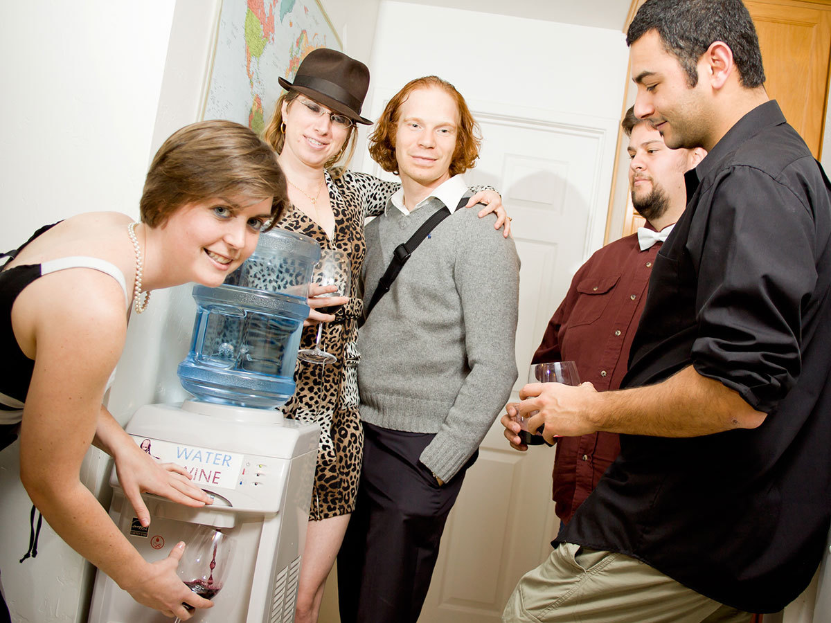
At the last minute before the party, we made it work, but it wasn’t pretty. The wine container sat on a shelf behind the cooler while the guts of the system sat on the floor —all of it draped with sheets, making it obvious that some shenanigans were taking place. The partygoers were still impressed, and the effect was certainly delivered. But with our improved intuitions about fluid dynamics, we vowed to remake the Water-to-Wine Cooler as the awesome contraption it deserved to be.

We brainstormed by drawing block diagrams until we found a simple design we liked, then we shopped for a water cooler. An important requirement was the ability to electrically capture the mechanical action of the dispense button, covertly. We eventually found a GE water cooler that was perfect. It had hot and cold sides, so we could dispense wine out of the cold side, and for those in the know, room-temperature water from the hot side. We figured we could finish the project that same day; it ended up taking a couple weekends.

For the gurgling effect, we tried pumping air into the water bottle, without letting any water flow out. But we quickly saw that the excess pressure would have no place to go, unless we put a small vent in the top of the bottle — and if we did, water would back-flow through the air pump and start a siphon. Again.

Our solution was to hide an identical water bottle below, for the top one to drain into. This lets the water level decrease over the course of the party, which is more realistic. When the water gets low, you just swap the bottles, and you’re back in business. For easy during-party maintenance, we added a fill port for the wine and LED indicators to notify us if something needs attention.

The finished Water-to-Wine Cooler is indistinguishable from a normal water cooler, and we can stand at a distance and chuckle as our unsuspecting friends go from shock, to bewilderment, to amusement.

W2W Design

In the unmodified GE cooler, the inverted jug on top empties into a reservoir with two pipes coming out, one to the refrigeration unit and the other to the heating element. We rerouted one pipe directly to the hot water tap, and the other one to a gravity valve that controls flow to the second jug hidden inside the bottom of the cooler.

We also added a plastic reservoir that holds the wine for dispensing, a switch triggered by the cold water button, and the electronics and hydraulics to translate a button press into a simultaneous draining of water into the lower jug, and pumping of wine up into the cold-water tap.

Control comes from an ATmega AVR microcontroller development board with 4 relay outputs. The inputs to the board are a small switch triggered by the cold water tap, a water-empty float switch, and a wine-empty float switch. On the output side, 2 relays control the water drain valve solenoid and the pump that dispenses the wine. The board also controls 3 LEDs, swapped in for the GE cooler’s original status LEDs, which flash to show that the software is working and indicate empty water and empty wine inside.

Finally, a wine-full float sensor connects directly to an LED that shines through a small hole in back, bypassing the microcontroller, to let you know when to stop pouring refill wine. The W2W has a lot going on inside, but after you remove the compressor and heater from inside the cooler body, and if you use a 3-gallon jug in the bottom instead of a 5-gallon, it all fits.

The result? A miraculous illusion where water glugs down from the bottle to emerge mysteriously from the spigot as wine. To throw your own sacrilegious party, check out these complete build instructions.

Downloads

Grab our Water to Wine (W2W) code for the AVR microcontroller: https://github.com/partyrobotics/water-to-wine or git@github.com:partyrobotics/water-to-wine.git


MAKE Volume 34: Join the robot uprising! As MAKE's Volume 34 makes clear, there’s never been a better time to delve into robotics, whether you’re a tinkerer or a more serious explorer. With the powerful tools and expertise now available, the next great leap in robot evolution is just as likely to come from your garage as a research lab. The current issue of MAKE will get you started. Explore robot prototyping systems, ride along with the inventors of the OpenROV submersible, and learn how you can 3D-print your own cutting-edge humanoid robot for half the price. Plus, build a coffee-can Arduino robot, a lip balm linear actuator, a smartphone servo controller, and much more

On newsstands now, by subscription, or available in the Maker Shed

Buy now!

Project Steps

Gather materials and tools.

For this project you’ll need to do some soldering, drilling, cutting, and simple microcontroller programming. Total project cost is about $300.

You’ll also need to grab our Water to Wine (W2W) code for the AVR microcontroller: https://github.com/partyrobotics/water-to-wine or git@github.com:partyrobotics/water-to-wine.git

Plan your attack.

Here’s the block diagram that shows how all the components of the system interact.

And here’s the layout diagram showing where all the secret components will go inside the cooler.

Disassemble the cooler.

First, remove the top cap on the water cooler with a half turn.

Remove all visible screws in the cooler, and strip it of all excess insulation, tubing and wiring. Don’t throw anything out yet; you’ll need some of it later.

CAUTION: The metal chassis can be sharp, so take care not to cut yourself.

Work with a friend, as extra hands will come in handy. We took our time, about 3 hours picking apart the guts, and it was fun seeing how the water cooler works and how its mechanisms inside are packaged.

TIP: To keep track of where the small screws come from, it helps to label pieces of duct tape and add the screws to the sticky side.

Remove the compressor and water heater.

Refrigerant compressors made before 1995 may contain chlorofluorocarbons (CFCs), which harm the ozone, so you need to take them to a refrigerator repair shop where they can safely evacuate those gases.

Our compressor was new and contained R134A refrigerant, which is not illegal to vent, but still contains greenhouse gases. I used heavy bolt cutters to cut and quickly crimp the copper tubing to minimize leakage.

WARNING: This is a job best done outdoors, and you should avoid inhalation and skin contact.

If in doubt about your compressor, call a local refrigerator repair shop or learn more at epa.gov.

Remove the water reservoir and LEDs.

Remove the water reservoir (surrounded with foam insulation) and set it aside; you’ll reuse it.

Finally, remove the LED assembly behind the front panel. You’ll substitute your own LEDs. You should be left with an empty chassis.

Mount the hidden switch.

Add a 4″ extension to the mini lever switch and superglue it in place. We used a scrap of aluminum sheet cut with tinsnips. If your switch has a roller on the lever, that can be a useful attachment point.

The hot and cold dispense buttons activate the valves inside by pushing plastic sliders. Position the switch body on the plastic bracket on the hot water side, so that the cold water slider will click down its lever. Make marks for its mounting holes.

To secure the switch, drill and tap #2-56 screw holes. We used metal screws, but plastic screws would probably be better because the plastic is pretty soft.

Screw the switch into place and make sure you get reliable clicks when the button is pressed from the outside.

Prepare the float sensors.

Make the float extensions by cutting 1/2″ acetal tubing: a 4” length for the water sensor, a 3/4″ length for the “wine is full” sensor, and a 4-1/2″ length with a 2″ right-angle extension for the “wine is empty” sensor. For this extension, drill the main tube, or miter both tubes, then glue the extension on with silicone.

Thread the bottom of each tube with an M8 tap, and screw each sensors into its tube, feeding the wires through.

Build the wine reservoir.

Use a step drill to make a 1-1/8″ hole in the cooler’s back cover for a bulkhead fitting, and another small hole for the “wine is full” LED to shine through.

TIP: Step drills are great for drilling thin material. They make much cleaner holes than spade bits or hole saws.

The wine reservoir is made of polypropylene, which has a great combination of chemical resistance, availability, cost, and workability. It’s usually milky in color and marked with the number 5.

In the bottom of the reservoir, drill a 1-1/8″ outlet hole and mount another bulkhead fitting. Keep placement in mind because you’ll need to make a matching cutout in the metal shelf it sits on.

Drill a hole in the side of the reservoir to fit the “empty” right-angle float sensor. It’s best to make this hole high up on the container to minimize potential leaks.

Drill 2 holes in the lid: one for the “full” float sensor, the other for the wine fill tube. Both holes should roughly match up with holes in the plastic shelf above.

Mount the wine float sensors and use silicone glue to seal any gaps.

Modify the metal shelf.

Make 4 holes in the water cooler’s lower, metal shelf: 2 to match the holes in the pump container lid (make sure there’s space for the pump outlet barb to poke through), one for the pump connector to pass through, and one for the flex riser to pass through.

Use a Dremel or other high-speed rotary tool to make a cutout in the metal shelf for the wine reservoir’s bulkhead fitting.

Enclose the wine pump (optional).

The wine pump sits in a plastic snap-lid container of its own, surrounded with bubble wrap to quiet it down. This is optional since the pump comes with its own mounting bracket, but silencing the pump improved the illusion.

Make 2 holes in the pump container, one for the wine inlet and one for the pump wires.

Make 3 holes in the pump container lid: one for the pump outlet, and 2 for machine screws that will suspend the container under the cooler’s metal shelf.

Replace the LEDs.

For the W2W status indicators, use the cooler’s original front indicator panel, swapping in your own green, blue, and red LEDs and their matching resistors.

On the LED circuit board, desolder the LEDs and resistors, and clip off the diodes. Solder your new green, blue and red LEDs in place, adding 560Ω, 1kΩ, and 390Ω resistors, respectively. Crimp a 4-pin connector to the wire bundle and install the board back in place with 2 screws.

Wire up the power supply.

Solder the end of a standard power cable to the power cord wires inside the water cooler.

Connect the cooler’s original power switch to the output side of your power adapter, using spade connectors.

Insulate all individual wire connections, and each bundle, with electrical tape or heat-shrink tubing.

Wire up the microcontroller board.

Polarity doesn’t matter for the mini lever switch, gravity valve, and float switches, so you can solder a same-color wire pair to each of these components. Then connect matching wire pairs to the control board’s screw terminals, as seen here in yellow, white, and green.

The pump wires are polarized, so connect a different-color wire pair here — in our case brown for power, black for ground.

Crimp Molex connectors onto all wire pairs, so you can plug the matching pairs together. This makes the cooler easy to disassemble for cleaning and maintenance, and foolproof to reassemble.

Solder and crimp a connector for the power input to the logic board that matches the output of the power supply brick.

In the center of the board, connect the blue, red, and green LEDs, respectively, to GPIO pins PA7, PA6 and PA5. The black wire goes to ground.

NOTE: Since all the inputs are used up, you’ll wire the “wine is full” float sensor directly to the LED pointed out the back of the cooler, later in Step 23.

Adjust the pump voltage (optional).

We had to play with our pump voltage to get the desired speed. Although the pump was rated for 12V, using 5V gave us the perfect flow rate to match the water flow rate. So, we soldered a 7805 voltage regulator on the board to get us there. The gravity valve runs directly off 12V.

In this photo, all red wires are power, all black wires are ground. The heavy red and black wires extending to the top are 12V and ground coming into the board.

Along the right edge in this view, the red wires are tying one end of the terminal block high, to 5V, so that when a float sensor is triggered and closes its circuit, the microcontroller can detect a signal going high.

The black wire below and to the left of the chip is the grounding of the black LED wire from Step 13.

The voltage regulator hanging off the board gets 12V from the red and black wires going to it, and has 10µF electrolytic capacitors on both the input and output for stable operation.

It may be useful to refer to the board schematic: https://www.olimex.com/Products/AVR/Development/AVR-IO-M16/resources/AVR-IO-M16-SCH-REV-A.pdf

Mount the water reservoir.

Wrap Teflon tape around the end of the metal tube going to the cold water valve. Attach a 34″ length of 3/8″ tubing and use a hose clamp lined with a thin piece of rubber to secure it in place. The other end of this tube will connect to the pump’s output barb.

Similarly, clamp a 23″ length of 3/8″ tubing to the metal tube coming out of the side of the water reservoir. The other end of this tube goes to the input of the gravity valve.

Replace the water reservoir in the chassis. Attach the opaque white tubing coming from the hot water valve to the bottom of the reservoir, using 2 small zip ties to secure it.

Attach the float sensor with a 4″ extension to the tube inside the water reservoir using a ziptie. Feed the wires through the tube and crimp a connector on.

Attach the water sensor.

For the “water is empty” sensor, attach a straight float sensor to the metal vent tube that runs into the water reservoir.

Anchor the sensor with a zip tie, and run its wires out through the tube.

Mount the pump.

Connect the power supply and attach the pump lid underneath the metal shelf using 2 machine screws and nuts.

Stuff the pump container with bubble wrap or foam around the pump and use the flaps of the lid to lock the container in place.

Attach the tube coming from the cold water valve to the pump outlet.

Mount the gravity valve.

Feed the gravity valve’s wires up through a corner hole in the plastic shelf, and then mount the valve in the hole. Attach 1/2″ couplers on both sides using Teflon tape.

Run the flexible sprinkler riser from the bottom coupler through the hole in the metal shelf.

Attach a 3/8″ barbed fitting to the top coupler and connect the hose coming from the water reservoir to it.

Mount the wine reservoir.

Attach a 3/8″ barbed fitting to the bulkhead and glue it in place with silicone, since the inner threads are straight and not tapered.

Set the assembly on the metal shelf and connect a 14″ length of 3/8″ tubing from the bottom barb to the wine pump inlet.

Attach the microcontroller board.

Download the W2W code from GitHub at git@github.com:partyrobotics/water-to-wine.git or https://github.com/partyrobotics/water-t… and then upload it to the microcontroller.

Attach standoffs to the logic board and use double-sided tape to attach it to the inner wall of the chassis in an accessible spot.

Mate all the connector pairs. Connect the switch and reattach the top cover.

Add the secret water jug.

Put a 3gal water bottle in the lower compartment with the flex riser going to it from the gravity valve. Unfortunately, the standard 5gal size doesn’t fit, so use the 3gal size for easy swapping.

Connect the wine fill port.

Assemble the back cover by attaching a bulkhead fitting through the large hole and attaching a right-angle barbed fitting to the bulkhead.

Attach a length of tubing to reach down about halfway into the wine reservoir, about 10″.

Attach the “wine is full” LED to the water reservoir using duct tape. Connect the LED to the float sensor in the wine reservoir lid and make sure it lines up with the hole in the back cover.

Attach the cover and grate with their original screws.

Make the refueling funnel.

Slip-fit about 8″ of tubing onto the bottom of the funnel, and on the other end attach a 3/8″ barb to a 1/2″ NPT fitting. This threaded end fits into the wine port bulkhead for party in-flight refueling.

Fill … and empty.

Power up the machine. All the lights flash briefly to let you know the code is running properly and all the LEDs are hooked up. The code implements a simple state machine with all the inputs and outputs. There are 5 main states: Idle, Dispense, Out of Water, Out of Wine, and Out of Water & Wine.

The top green LED is on whenever the machine is on. The blue LED lights up when water is out, and the red LED when wine is out.

Test that the sensors turn the appropriate LEDs on, then fill with water and wine, checking for leaks. The first time the pump is run, it will take about 30 seconds to prime; this is normal.

Conclusion

“But I Just Wanted Water!”

We took the W2W to a “cocktail robotics” event called Barbot, at the DNA Lounge in San Francisco. Several contraptions were dispensing all kinds of alcoholic concoctions, and attendees bought RFID “coins” that they would insert into the different machines for their drinks to be dispensed.

Our RFID reader wasn’t working, so we served as the “RFID readers” for the Water to Wine. On a couple of instances, someone would come up and mutter under their breath, “Oh, thank goodness, water!” only to be disappointed. One woman came up to the machine and dispensed wine into her cup. Her eyes widened, and she apologetically said, “But ... but I just wanted water.” She seemed defeated. We always laughed and pointed out that the hot water button would dispense plain water, but no one ever tried out the hot water button on their own.

This project first appeared in MAKE Volume 34 in the Build Notes section.