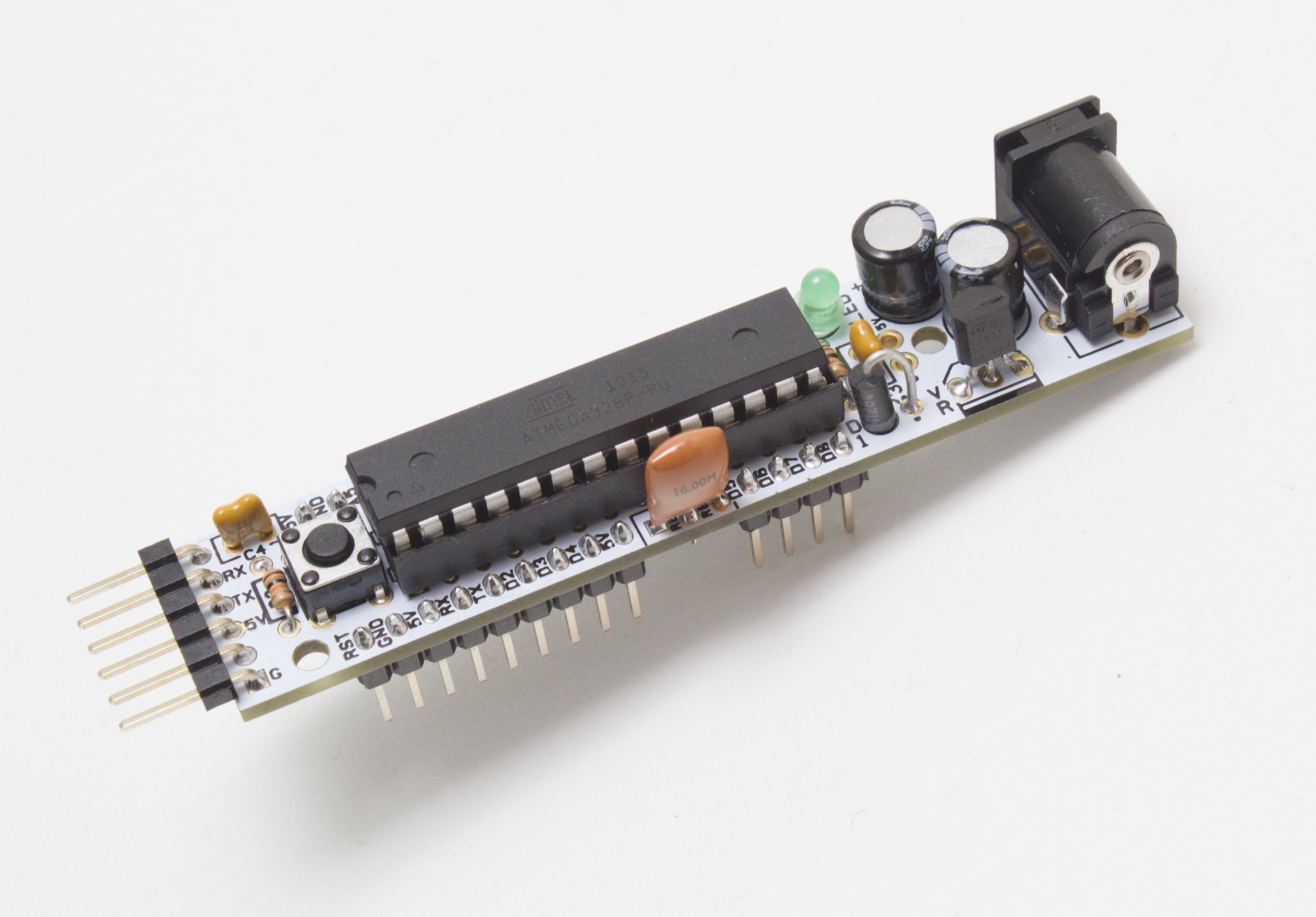
There are many tools for creating printed circuit boards, from the open source KiCAD to various online services. CadSoft’s EAGLE is a favorite in the open hardware community. Here you’ll learn the basics of PCB design in EAGLE, plus how to build the essential core of an ATmega microcontroller board.
The Really Bare Bones Board (RBBB) and its schematic were originally designed by Paul Badger of Modern Device. It’s pretty much the bare minimum needed for a useful Arduino-type development board. And once you build the schematic in EAGLE, it’s easy to incorporate in other designs.
NOTE: The part list, to right, gives the bill of materials for a single RBBB, but you don’t really need the components on-hand to follow along with the design tutorial below.

Using EAGLE
EAGLE is a collection of programs, each serving one part of the design process. We’ll focus on Schematic Editor and Board Editor; other modules include Autorouter (trace layout AI), Parts Editor, CAM Processor (for creating machining-ready files), and a scripting interface for writing ULPs (User Language Programs).
Components are chosen from the parts library. Parts always have two representations: one for the schematic and one for the board. Most components come in different physical “packages,” and EAGLE’s libraries allow multiple packages to be associated with the same schematic symbol. To simplify things, I’ve created a custom RBBB library that includes only the parts in the packages you’ll need. Once you’re comfortable, SparkFun’s library is a good place to start expanding your horizons.
EAGLE DESIGN WORKFLOW
- Design and sourcing: Find parts, read datasheets, download or draw footprints.
- Schematic Layout: Connect parts electrically with signals.
- Electrical rule Check (ErC): Run an AI helper to identify schematic errors.
- Board Layout: Place parts on the board and draw the actual traces connecting them.
- Design rule Check (DrC): Run an AI helper to identify layout errors.
- Generate Gerber and drill files: Run CAM Processor to generate machining files.
PCB design takes several stages. This article guides you as far as drawing and validating the schematic, which should be enough to whet your appetite. The next piece in the series takes you through BLAH BLAH BLAH, and finally, part 3 wraps it up with BLAH BLAH BLAH.


