FM153838jb

For more on microcontrollers and wearables, check out Make: Volume 43.  Don't have this issue? Get it in the Maker Shed.
For more on microcontrollers and wearables, check out Make: Volume 43.
Don’t have this issue? Get it in the Maker Shed.

We live on a small island with a large population of rats. Since we’re opposed to capital punishment of uninvited guests, even furry ones, we try to catch them with live traps when they sneak inside. After years of failed attempts with store-bought traps, we realized we had to make a trap as clever as the rats.

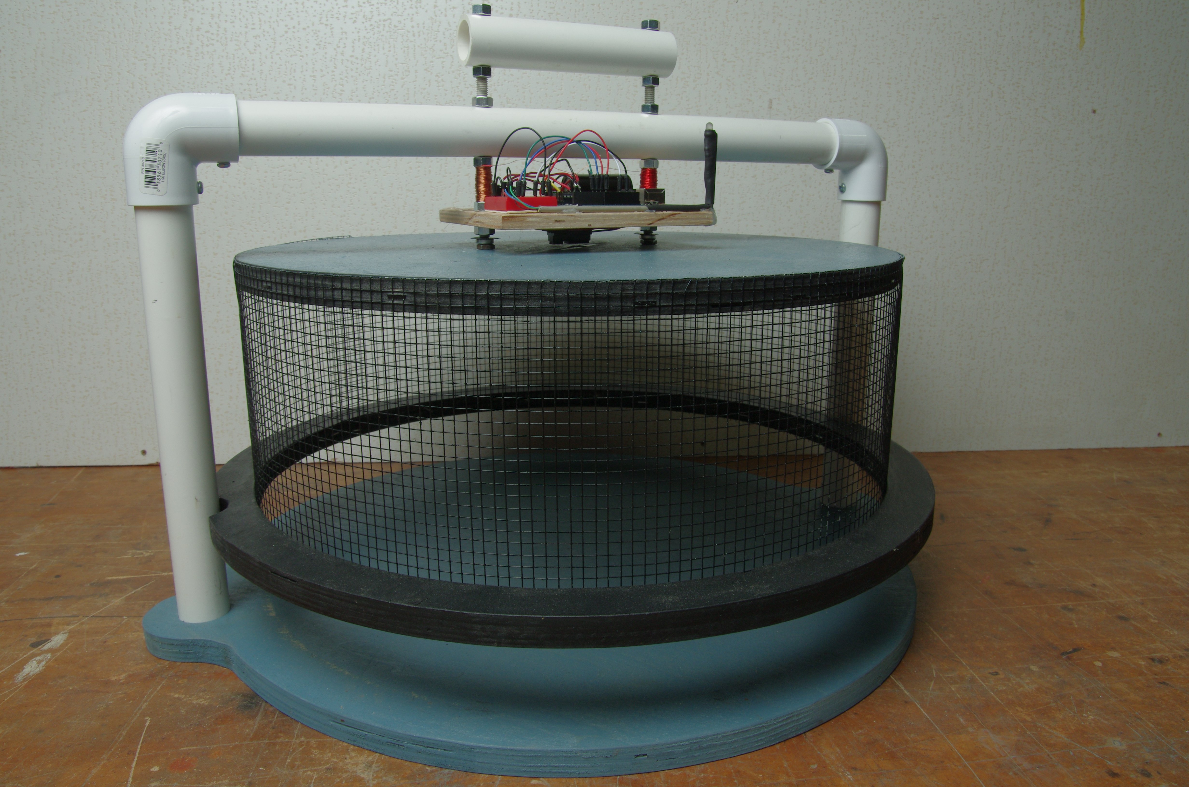
Rather than an enclosed cage, which they seem to avoid, we used a suspended basket that leaves an unobstructed view at rat eye level. The cage is suspended by two neodymium magnets. When an infrared proximity sensor detects a rat below, it triggers two electromagnets that repel the suspension magnets, dropping the cage over the rat.

Over several years (and rats), the trap has gradually improved. The sensitivity is recalibrated every 10 minutes in software running on an Arduino. An RGB LED indicates trap status, a buzzer sounds the alarm when something gets caught, and a handle makes it easy to carry.

Project Steps

Build the cage

Mark out your plywood as shown in the cutting diagram.

TIP: To draw perfect circles on plywood, put a small nail in the center and use a stiff wire with a crook at each end to keep your pencil in place as you draw the circle.

Drill holes

Using hole saws or Forstner bits, drill the two 1-5/16″ holes in the base and the two 15/8″ holes intersecting the cage rim.

Drill two 5/16″ holes in the middle of the cage top, the same distance apart as the emitter and receiver on your sensor (about 3/4″). Then drill two 1/4″ holes in the top, 5″ apart and in line with the sensor holes; these are for mounting the disc magnets.

Cut the plywood

Using a jigsaw, cut out the base, rim, and top. (Drill a hole first to get the blade started.) Touch up with 120-grit sandpaper.

Assemble the cage

Wrap a 7″×58″ strip of metal mesh around the cage top and staple in place. Staple the other end of the mesh cylinder into the cage rim. If your rodents are voracious chewers, staple a small piece of screen over the sensor holes inside the cage.

Paint (optional):

Give the base and cage a coat of paint or two to make it look snappy.

Build the support frame

Cut your PVC pipe into 4 sections: a 19-5/8″ crossbar, two 12-1/4″ uprights, and a 6″ handle.

TIP: Make a drilling jig to prevent your pipe from rolling when you drill. Just drill through a small block of wood using a bit the same diameter as your pipe.

Drill two 5/16″ holes 5″ apart through the handle. Drill a matching pair centered in the crossbar.

Use 2 PVC elbows to attach the crossbar to the uprights, making sure the bolt holes are parallel with the uprights. Drill pilot holes and fasten the elbows with 3/4″ #8 pan head screws. (You could use cement, but screws make it removable.)

Make the electromagnets

Wind 2 nuts onto each threaded rod, 1″ apart, 11/16″ from one end. Wrap electrical tape over the threads between nuts.

Measure out 35′ of magnet wire. Tape it to the threaded rod between the nuts, leaving 6″ of extra wire (wrap this around the bolt shaft out of the way for now).

Chuck the threaded rod in your drill, and cover the exposed threads with masking tape so they won’t damage the wire’s insulative coating. Now carefully wind the wire on between the 2 nuts. Secure it with a layer of tape, again leaving 6″ of wire hanging out.

Repeat for the other electromagnet, making sure the direction of winding is the same.

Test polarity

Hook each electromagnet up to a 12V power source briefly, with the lead from the outside of the coil connected to positive (+). Use a magnetic compass (or smartphone compass app) as shown to determine the magnet’s polarity. Record which end of the compass needle (south or north) points toward the active electromagnet.

Connect the electronics

Cut a 6″×5-1/2″ rectangle of 3/8″ plywood. Drill a pair of 5/16″ holes through it, 5″ apart.

Use small beads of hot glue to attach the Arduino, capacitor, and 5V relay onto the platform board. If you’re using a speaker, glue that on too.

Wire the breadboard

Stick a mini breadboard onto the platform next to the Arduino. Wire the transistor as shown in the wiring diagram, with the 1kΩ current-limiting resistor between its base and the Arduino pin D12.

For audio and visual feedback of trap status, add the RGB LED and speaker as shown. Holding the RGB LED with the longest leg second from the left, the pinout from left to right is Red, Common Cathode, Green, Blue. Solder a 100Ω resistor to the common cathode and a 50Ω resistor on the red leg. Put a small piece of heat-shrink tubing over each leg (including the resistors. Then shrink a larger piece over them all. Connect the cathode to ground, the red leg to D7, green to D6, and blue to D5 on the Arduino.

Connect the speaker between GND and D8.

Solder the diode and capacitor

Solder a silicon power diode between the capacitor’s negative (–) terminal and the relay’s common (COM) terminal; the diode’s cathode (marked with a line around the diode) should be connected to the relay.

Solder the relay

Run a wire from the capacitor’s positive (+) terminal to the relay’s normally open (NO) terminal. Solder another wire onto the same relay terminal and plug it into the Arduino’s Vin pin.

Solder a silicon power diode across the relay’s coil. Solder a wire to the relay pin where the diode’s anode is attached, and connect the other end to the transistor’s collector at the breadboard. Run a wire from the other relay coil terminal (cathode side of the diode) to the Arduino’s +5V pin. Strip this end a little extra long so you can solder another wire to it.

Wire the sensor

Your sensor should have a 3-pin female plug on the end of its lead. Cut 3 pieces of appropriately colored hookup wire, and use these to extend your sensor’s leads. Plug the black lead into the Arduino’s GND, and the yellow lead (signal) into A1. Solder the sensor’s power wire to the relay power wire at the Arduino’s +5V pin.

Glue the sensor onto the bottom of the electronics platform, making sure the infrared emitter and receiver match the 2 holes drilled in the top of the cage.

Install the electromagnets

Insert the 2 threaded rods into the holes in the electronics platform and secure them with nuts underneath.

Cut the electromagnet leads to length. Use a mini torch, lighter, or sandpaper to remove the shellac from the ends of the leads.

Solder the leads from the outside of both electromagnets’ windings to the relay’s common (COM) pin.

Solder the wires from the inside of the coils onto the capacitor’s negative (–) wire at the Arduino’s GND pin.

TIP: Sharing a Pin Header

It’s often useful to get more than one wire into a header pin. To do this, strip one of the wires extra long (make sure it’s solid core). Wrap and solder the ends of any additional wires onto the upper part of your stripped section, and then plug the lower part into the header. To prevent shorts to nearby objects, the soldered joint can be enclosed in heat-shrink tubing.

Final assembly

Insert the PVC frame into the holes in the base. From the underside of the base, drill 2 pilot holes from the inside of each pipe, then secure the pipe with #8 pan head screws.

Attach electronics and handle

Slide the electronics assembly’s threaded rods up through the holes in the horizontal crossbar. Thread down 2 nuts to clamp it in place. Use 4 more nuts to attach the handle on top.

Install the permanent magnets

Thread two 1/4″×1″ bolts through the holes in the top of the cage. Secure with 2 nuts on the bottom.

Test the polarity of 2 neodymium magnets, then snap them onto the bolt heads, oriented so they’ll repel the electromagnets. For example, if the electromagnets’ north pole is down, then the permanent magnets’ north pole should face up — like repels like.

Finally, squeeze the cage into place between the support posts.

Program the Arduino

Download the Arduino sketch from github.com/Photosynthesis/make-smart-rat-trap and upload it to the board.

Test!

Slide the cage up until it snaps onto the magnetic supports, then plug your AC/DC adapter into the Arduino’s power jack. The LED will blink green while the Arduino calibrates the sensor’s threshold, then turn solid green once it’s set and ready to trigger.

Test the trap by slipping a rodent-sized object under the center of the cage. The LED will flash red and the Arduino will close the relay with a click to fire the electromagnets, dropping the cage. A blue LED means the trap has been triggered and may contain a rodent.

If the relay clicks but the trap doesn’t drop, don’t worry. Your magnets are probably too strong for the electromagnets to counteract. Cut some small squares of tape and stack them on top of your permanent magnets until they’re weak enough to be dislodged.

Your trap is done!

Conclusion

Get Trapping
Though designed for rats, the trap can be used to catch mice, squirrels, or other small animals. Place the trap in a rodent-infested area, sprinkle some attractive bait below the sensor (we’ve had success with combinations of chocolate, peanut butter, raisins, and nuts), and power it on. Happy trapping!